A transmissive wavefront adjusting device

An adjustment device and transmission type technology, which can be applied to exposure devices of photolithography process, microlithography exposure equipment, instruments, etc., can solve problems such as low calibration accuracy, and achieve the effect of ensuring decoupling and improving calibration accuracy.

Active Publication Date: 2021-12-31
CHANGCHUN INST OF OPTICS FINE MECHANICS & PHYSICS CHINESE ACAD OF SCI
View PDF0 Cites 0 Cited by
  • Summary
  • Abstract
  • Description
  • Claims
  • Application Information

AI Technical Summary

Problems solved by technology

[0006] The purpose of the present invention is to provide a transmission wavefront adjustment device, which can effectively solve the problem of low correction accuracy

Method used


Image

  • A transmissive wavefront adjusting device
  • A transmissive wavefront adjusting device

Examples


Embodiment Construction

[0021] In order to make the above objects, features and advantages of the present invention more comprehensible, the specific implementation manners of the present invention will be described in detail below in conjunction with the accompanying drawings.

[0022] In the following description, specific details are set forth in order to provide a thorough understanding of the present invention. However, the present invention can be implemented in many other ways than those described here, and those skilled in the art can make similar extensions without departing from the connotation of the present invention. Accordingly, the present invention is not limited to the specific embodiments disclosed below.

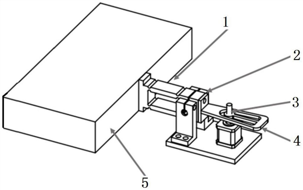
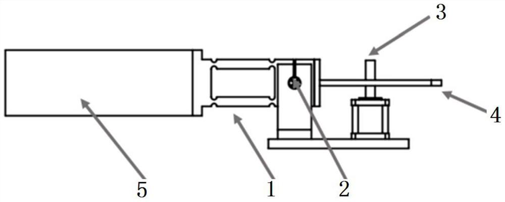
[0023] Please refer to figure 1 and figure 2 , figure 1 A schematic structural diagram of a transmissive wavefront adjusting device provided for a specific embodiment of the present invention; figure 2 for figure 1 Schematic diagram of the main view structure.

[0024] A ...


PUM


Abstract

The invention discloses a transmission wavefront adjustment device, which comprises: a parallelogram mechanism, a flexible hinge, a flexible moment applying mechanism, a linear drive mechanism and a support, one side of the parallelogram mechanism is connected with one side of a mirror surface, and the parallelogram The other side of the mechanism is connected to the flexible moment applying mechanism, and the side of the parallelogram mechanism connected to the flexible moment applying mechanism is hinged on the support through a flexible hinge, and the linear drive mechanism is used to control the up and down deformation of the flexible moment applying mechanism, and then An edge moment is applied to the mirror by a parallelogram mechanism. Among them, through the flexible torque application mechanism, not only the linear motion of the linear drive mechanism can be converted into torque, but also has the characteristics of motion decoupling. In addition, through the parallelogram mechanism, the decoupling of the applied torque can be guaranteed, that is, no additional motion is added, and the torque is simply applied. Secondly, flexible hinges are used to ensure that the system has no empty back, hysteresis, etc., thereby improving the calibration accuracy.

Description

technical field [0001] The invention relates to the field of wavefront correction devices, in particular to a transmission wavefront adjustment device. Background technique [0002] Considering the influence of processing technology, environmental adaptability and assembly technology, the precision maintenance ability of the system itself is becoming more and more difficult to meet the imaging quality requirements of future precision optical equipment. [0003] Taking the lithography machine as an example, in order to achieve the diffraction limit, the optical error of the system itself needs to be close to and negligible. This requirement is almost impossible to achieve only by system processing and assembly. Therefore, it is necessary to use optical path compensation components to make the system reach the diffraction limit. [0004] Traditional active optics or adaptive optics mostly adopt the bottom push-pull structure, and adjust the optical path by changing the sagitt...

Claims


Application Information

Patent Timeline
Patent Type & Authority Patents(China)
IPC IPC(8): G02B26/00G03F7/20
CPCG02B26/00G03F7/70191
Inventor 安其昌张景旭李洪文刘炎森唐境
Owner CHANGCHUN INST OF OPTICS FINE MECHANICS & PHYSICS CHINESE ACAD OF SCI
Why Eureka
Try Eureka