High current circuit

A high-current, circuit technology, applied in motor vehicle high-current circuits, start-stop-automatic circuits, and high-current resistance fields, can solve problems such as inappropriate applications for a large number of applications, complex manufacturing of high-current circuit boards, and ohmic losses.

Pending Publication Date: 2021-07-23
AUTO KABEL MANAGEMENTGMBH
View PDF0 Cites 0 Cited by
  • Summary
  • Abstract
  • Description
  • Claims
  • Application Information

AI Technical Summary

Problems solved by technology

This high current carrying capacity requires large conductor cross-sections, which cannot usually be realized on circuit boards
Complex high-current circuit boards with conductive substrates are known, however, these high-current circuit boards are very complex to manufacture and are therefore unsuitable for a large number of applications
On the other hand, there are significant ohmic losses due to high currents, whose Joule heat has to be dissipated

Method used


Image

  • High current circuit
  • High current circuit
  • High current circuit

Examples


Embodiment Construction

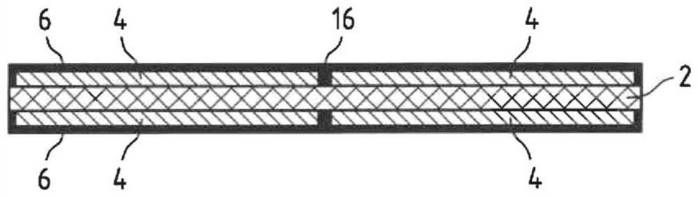
[0054] figure 1 A cross-section of a circuit board with a substrate 2 is shown. Substrate 2 may be fiber reinforced epoxy. Substrate 2 is in particular non-conductive. The substrate 2 is here a conventional substrate for circuit boards.

[0055] A conductor layer 4 is applied to the substrate 2 . The conductor layer 4 is in particular a copper layer. The conductor layer 4 is generally thinner than 1 mm and is brought into the desired topology by exposure and etching during the production of the printed circuit. Conductor layer 4 is covered by insulating layer 6 . The insulating layer 6 can be, for example, a solder resist varnish. At locations where the conductor layer 4 is to be contacted, the insulating layer 6 can be removed and / or the conductor layer 4 can be led out of the insulating layer 6 there. Thus, for example, contact pads can be applied to the conductor layer 4 . figure 1 The structure of the medium circuit board is conventional as it is used in standard c...


PUM


Abstract

The invention relates to a high current circuit with a circuit board consisting of a non-conducting substrate 2, a conductor layer 4 applied on the substrate 2 and an insulation layer 6 applied on the conductor layer, wherein contact pads 8, 10, 12, 20, 22, 24 breaking through the insulation layer 6 are arranged on either side of the circuit board and the contact pads 8, 10, 12, 20, 22, 24 are connected to one another through the substrate 2 by vias 14 and the vias 14 are arranged in the surface of the contact pads 8, 10, 12, 20, 22, 24, characterized in that at least one first of the contact pads 8 is arranged on a first side of the circuit board and a first semiconductor switch 28 on a second side of the circuit board is directly connected to at least one second of the contact pads 20, and that the semiconductor switch 28 is connected to the first contact pad 8 directly through the vias 14 and to the second contact pad 20, without further conductor tracks.

Description

technical field [0001] The invention relates to a high current circuit, especially a high current circuit of a motor vehicle, especially a high current switch, a controlled high current resistance and a start-stop-automatic circuit. Background technique [0002] The ever-increasing number of electrical components in modern vehicles leads to ever higher energy demands and consequently high current intensities. In this case, very high switching currents occur which are switched on by means of semiconductor switches such as MOSFETs or IGBTs. Two different challenges arise due to the high currents switched by means of these semiconductor switches. On the one hand, the current-carrying capacity of the circuit must be guaranteed, that is, currents up to several 100A must be able to flow through the circuit. Such high current-carrying capacities require large conductor cross-sections, which cannot usually be realized on circuit boards. Complex high current circuit boards with co...

Claims


Application Information

Patent Timeline
Patent Type & Authority Applications(China)
IPC IPC(8): H05K1/02H05K1/11H05K1/18
CPCH05K1/0206H05K1/0263H05K2201/10272H05K2201/09972H05K2201/0979H05K1/113H05K1/181H05K2201/10166H05K2201/0376H01L25/072H01L25/18H05K7/14329H05K7/1432H05K2201/0379H05K1/0212H05K1/0265H05K2201/10053
Inventor 乌多·克拉策大卫·卡西亚托雷
Owner AUTO KABEL MANAGEMENTGMBH
Why Eureka
Try Eureka