A frequency-tunable micro-scanning mirror and its application in fluorescence imaging

A mirror and micro-scanning technology, applied in the field of fluorescence imaging systems, can solve the problems of increased driving force, inability to precisely control the size of the field of view, and inability to synchronize scanning frequency, amplitude and phase adjustment, etc.

Active Publication Date: 2015-09-30
NINGBO MEIJING MEDICAL TECH
View PDF5 Cites 0 Cited by
  • Summary
  • Abstract
  • Description
  • Claims
  • Application Information

AI Technical Summary

Problems solved by technology

Since the frequency of the micro-mirror of the existing laser confocal probe is fixed and non-adjustable, when the confocal micro-scanning mirror probe is used for large-field imaging, the reflection area of ​​the micro-scanning mirror is the only thing that limits the objective lens to collect photons. Variable factors, so in order to improve the ability of the objective lens to collect photons, it is necessary to increase the reflective area of ​​the micro-scanning mirror, thereby increasing the driving force, resulting in increased energy consumption, and at the same time, the scanning frequency, amplitude and phase adjustment of the two micro-scanning mirrors cannot be adjusted. Realize synchronous process, resulting in low resolution of the final image, and the size of the field of view cannot be precisely controlled

Method used


Image

  • A frequency-tunable micro-scanning mirror and its application in fluorescence imaging
  • A frequency-tunable micro-scanning mirror and its application in fluorescence imaging
  • A frequency-tunable micro-scanning mirror and its application in fluorescence imaging

Examples


specific Embodiment

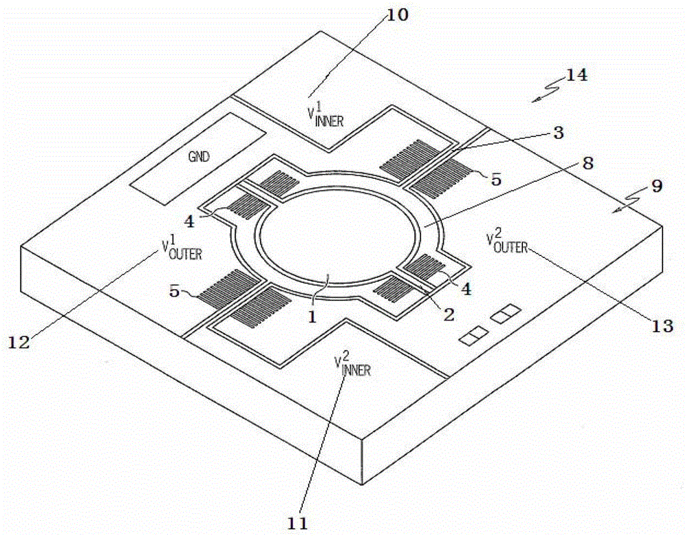
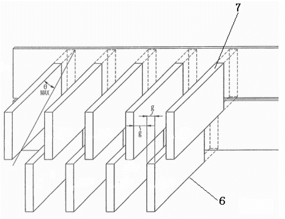
[0022] The present invention is a micro-scan mirror with adjustable frequency, such as figure 1 As shown, the reflector 1 is included, and the reflector 1 includes an inner shaft 2 for turning the reflector 1 up and down and an outer shaft 3 for turning the reflector 1 left and right. The reflector 1 is also provided with a first shaft for driving the inner shaft 2 to rotate. A group of comb-shaped driving devices 4 and a second group of comb-shaped driving devices 5 for driving the rotation of the outer shaft 3, such as figure 2 As shown, the first group of comb-shaped driving devices 4 includes a plurality of fixed stator combs 6 around the inner shaft 2 and a plurality of rotor combs 7 that can rotate at a certain angle around the inner shaft 2, and the second group of comb-shaped driving devices 5 includes a plurality of fixed stator combs 6 around the outer shaft 3 and a plurality of rotor combs 7 rotating at a certain angle around the outer shaft 3. The stator combs 6 a...


PUM

PropertyMeasurementUnit
thicknessaaaaaaaaaa
diameteraaaaaaaaaa
thicknessaaaaaaaaaa

Abstract

The invention discloses a frequency-adjustable micro-scanning reflector and application thereof in fluorescence imaging. The frequency-adjustable micro-scanning reflector comprises a reflector, and is characterized in that the reflector comprises an inner shaft for rotating the reflector up and down and an outer shaft for rotating the reflector to the left and the right, and is also provided with a first group of comb-shaped driving devices for driving the inner shaft to rotate and a second group of comb-shaped driving devices for driving the outer shaft to rotate, the first group of comb-shaped driving devices comprise a plurality of stator comb teeth fixed around the inner shaft and a plurality of rotor comb teeth capable of being revolved around the inner shaft by a certain angle, the second group of comb-shaped driving devices comprise a plurality of stator comb teeth fixed around the outer shaft and a plurality of rotor comb teeth capable of being revolved around the outer shaft by a certain angle, the stator comb teeth and the rotor comb teeth are staggered and distributed at intervals, and both the inner shaft and the outer shaft are provided with thermoelectric heaters for tuning the reflector. The invention has the advantage that the scanning frequency, amplitude and phase of the micro-scanning reflector can be adjusted, and while energy consumption is less, optical resolution cannot be decreased and the field of view cannot be reduced.

Description

technical field [0001] The invention relates to a fluorescence imaging system based on laser scanning, in particular to a frequency-adjustable micro-scan mirror and its application in fluorescence imaging. Background technique [0002] A fluorescence imaging system based on laser scanning, usually including a laser confocal probe for laser scanning fluorescence imaging, the laser confocal probe includes a laser diode, an effective photoelectric probe, two micro-scanning mirrors and an objective lens system. The field of view (FOV) of the confocal probe is determined by the size of the aperture of the objective lens. In addition, the ability of the confocal probe to collect fluorescent photons is also determined by the numerical value (NA) of the objective lens aperture. Since the frequency of the micro-mirror of the existing laser confocal probe is fixed and non-adjustable, when the confocal micro-scanning mirror probe is used for large-field imaging, the reflection area of...

Claims


Application Information

Patent Timeline
Patent Type & Authority Patents(China)
IPC IPC(8): G02B26/10G02B26/08G01N21/64
Inventor 张晓晶沈挺
Owner NINGBO MEIJING MEDICAL TECH
Why Eureka
Try Eureka