
Natural gas recovery process

A technology of natural gas and process, applied in the field of recovering light hydrocarbons and natural gas at the same time, can solve the problems of unstable reserves, inconvenient construction of fixed equipment for mining, energy waste, etc., to ensure normal and durable operation, facilitate long-term operation, The effect of reducing the amount of flash gas

Inactive Publication Date: 2013-06-12
四川金科深冷设备工程有限公司
View PDF4 Cites 9 Cited by
  • Summary
  • Abstract
  • Description
  • Claims
  • Application Information

AI Technical Summary

Problems solved by technology

[0002] It is known that for the natural gas in remote scattered wells, due to the small gas volume and dispersion, it is not convenient to build pipelines for centralized processing, and most of the wells cannot be exploited after exploratory wells
Many scattered wells have low air pressure and unstable reserves, which is not convenient to build fixed equipment for mining; a small amount of gas sources with certain pressure and high content of heavy components are often dehydrated with triethylene glycol, and throttle valves are used to throttle the flow by using the pressure of raw gas Decrease the pressure and lower the temperature to collect mixed hydrocarbons. After the hydrocarbons are collected, the natural gas cannot be further formed into products because the water dew point and hydrocarbon dew point are not up to the standard; affect production
In addition, many oil and gas treatment devices have natural gas that is vented and burned. On the one hand, it pollutes the environment and on the other hand causes energy waste. Enterprises bear a double economic burden

Method used


Image

  • Natural gas recovery process
  • Natural gas recovery process
  • Natural gas recovery process

Examples


Embodiment

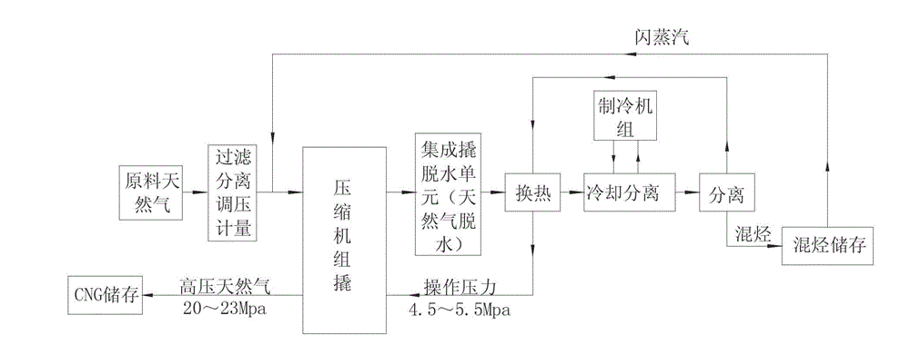
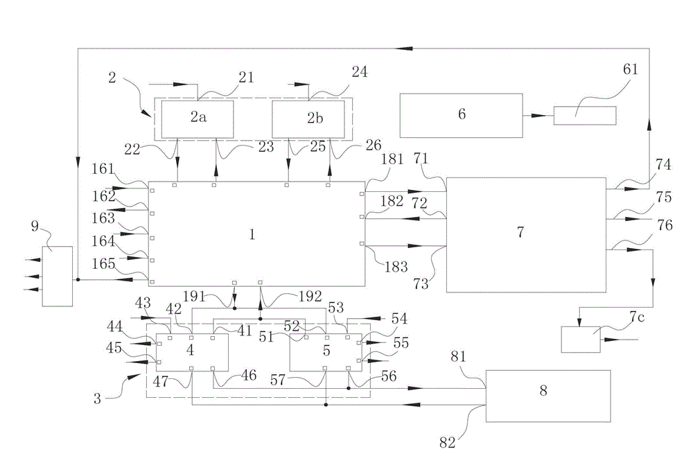
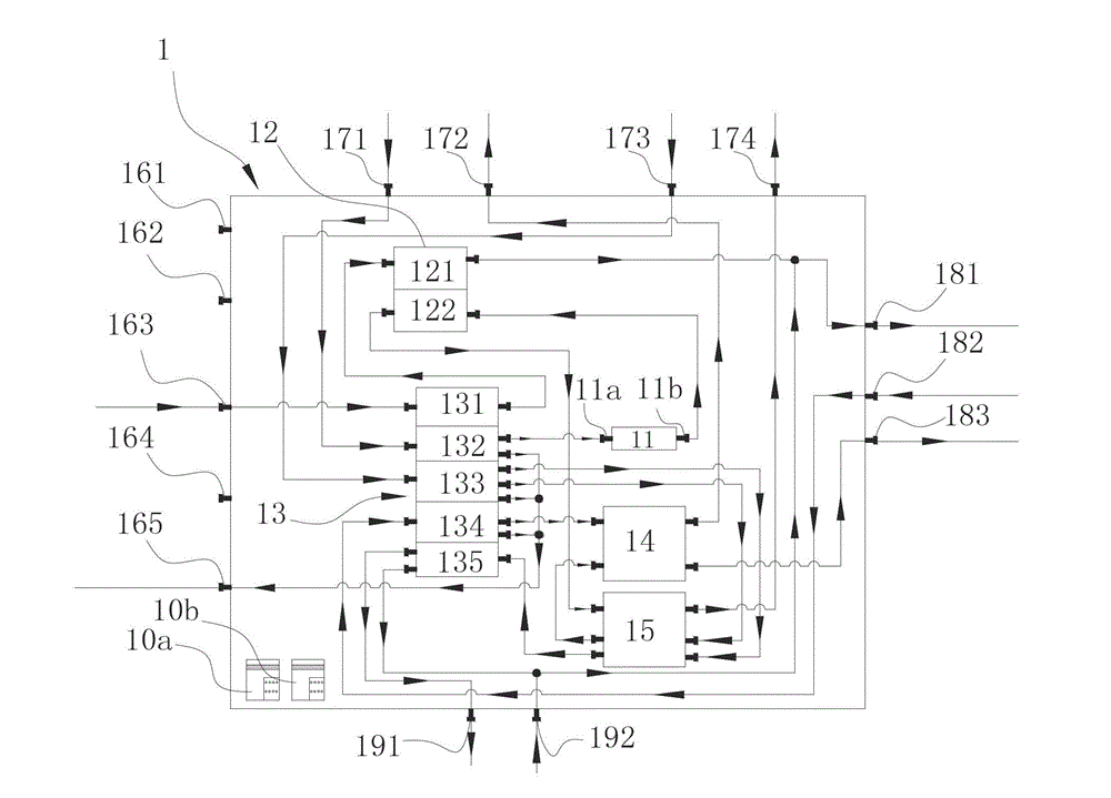
[0087] like figure 2 , 3 , 4, 5, 6 and 8 show that the equipment used in this embodiment to realize the natural gas recovery process includes compressor skid 7, integrated skid 1, refrigeration unit skid 2, mixed hydrocarbon storage loading skid A4, mixed hydrocarbon storage loading skid B5, air column 7c, instrument air skid 6, loading crane tube 8, three-phase separator 9. The integrated skid 1 includes a dehydration unit 11 , a filter unit 12 , a separator unit 13 , an air-air heat exchanger 14 , and a plate heat exchanger 15 . The compressor skid 7 includes a feed gas compressor 7a and a CNG compressor 7b.

[0088] Separator unit 13 includes inlet separator 131, normal temperature separator A132, low temperature separator 133, normal temperature separator B134, normal temperature separator C135; filter unit 12 includes low pressure dust filter 121, high pressure dust filter 122; refrigeration unit The skid 2 includes a high-temperature ice machine 2a and a low-temperat...


PUM


Abstract

The invention discloses a natural gas recovery process. The light hydrocarbon recovery rate can be improved, and energy consumption can be reduced by the natural gas recovery process. The process comprises the following steps of separating and filtering the material gas by a separator and a filter orderly, entering into a compressor to compress, air cooling, and then separating a part of water and heavy hydrocarbon through the separator; deeply dewatering through a dehydration unit until the moisture is smaller than 10ppm; filtering, pre-cooling to -10 DEG C through a heat exchanger, cooling to -35 DEG C by a refrigerator, then cooling and separating, and reheating the separated mixed hydrocarbon to normal temperature through the heat exchanger and then conveying to a mixed hydrocarbon storage tank; returning the separated gas to the heat exchanger to exchange heat; reheating the gas to the normal temperature, and then entering a CNG (compressed natural gas) to compress and store. By adopting the process, the material gas with low air pressure and unstable storage quantity can be collected; and the natural gas recovery process is high in recovery rate, low in recovery cost, simple in recovery equipment, simple and convenient to operate, and low in energy consumption.

Description

technical field [0001] The invention relates to a recovery process of natural gas as a raw material, in particular to a recovery process which is simple in process and capable of simultaneously recovering light hydrocarbons and natural gas. Background technique [0002] It is well known that for the natural gas in remote scattered wells, due to the small gas volume and dispersion, it is not convenient to build pipelines for centralized processing, and most of the wells cannot be exploited after exploration. Many scattered wells have low air pressure and unstable reserves, which is not convenient to build fixed equipment for mining; a small amount of gas sources with certain pressure and high content of heavy components are often dehydrated with triethylene glycol, and throttle valves are used to throttle the flow by using the pressure of raw gas Decrease the pressure and lower the temperature to collect mixed hydrocarbons. After the hydrocarbons are collected, the natural ga...

Claims


Application Information

Patent Timeline
Patent Type & Authority Applications(China)
IPC IPC(8): C10L3/10
Inventor 江代彬蔡以勇付南张卫忠
Owner 四川金科深冷设备工程有限公司
Learn More