
Overlay precision measurement mark and use method thereof

An overlay precision and marking technology, which is applied to measuring devices, optical devices, and scattering characteristic measurements, can solve the problems of increased production costs, large space occupied by measurement marks, and poor accuracy of overlay precision measurement. High precision and accuracy, good alignment and connectivity, and device space saving effects

Pending Publication Date: 2020-12-01
SHANGHAI HUALI INTEGRATED CIRCUTE MFG CO LTD
View PDF10 Cites 3 Cited by
  • Summary
  • Abstract
  • Description
  • Claims
  • Application Information

AI Technical Summary

Problems solved by technology

[0006] In view of the above-mentioned shortcomings of the prior art, the object of the present invention is to provide an overlay precision measurement mark and a measurement method, which are used to solve the poor accuracy of the overlay precision measurement and the occupation of the measurement mark in the prior art. The problem of large space and increased production cost

Method used


Image

  • Overlay precision measurement mark and use method thereof
  • Overlay precision measurement mark and use method thereof
  • Overlay precision measurement mark and use method thereof

Examples


Embodiment Construction

[0029] Embodiments of the present invention are described below through specific examples, and those skilled in the art can easily understand other advantages and effects of the present invention from the content disclosed in this specification. The present invention can also be implemented or applied through other different specific implementation modes, and various modifications or changes can be made to the details in this specification based on different viewpoints and applications without departing from the spirit of the present invention.

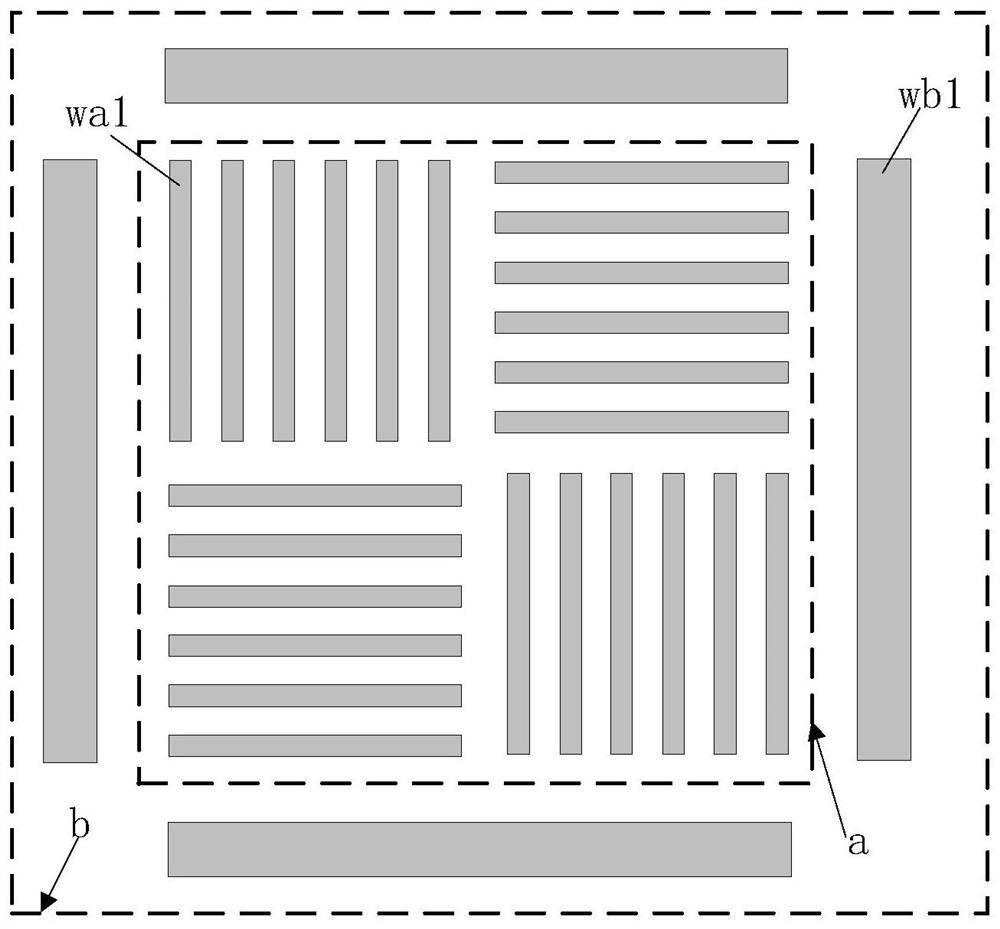
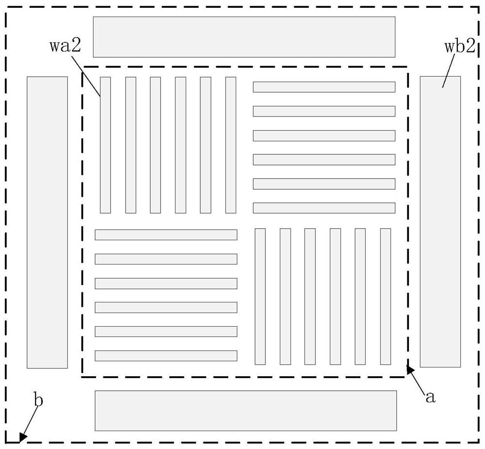
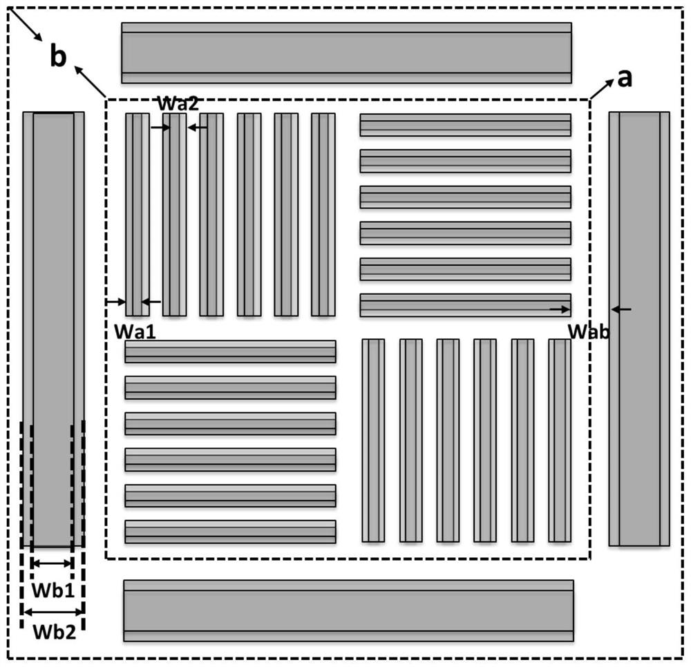
[0030] see Figure 1 to Figure 3 . It should be noted that the diagrams provided in this embodiment are only schematically illustrating the basic idea of ​​the present invention, and only the components related to the present invention are shown in the diagrams rather than the number, shape and shape of the components in actual implementation. Dimensional drawing, the type, quantity and proportion of each component can be changed arb...


PUM


Abstract

The invention provides an overlay precision measurement mark and a use method thereof, and aims at a photoetching current layer. The characteristics of DBO diffraction measurement are utilized, and aCDSEM measurement pattern does not participate in a diffraction result; after etching, the CDSEM measurement mark can be used for representing the performance of the overlay precision after etching, and the defect that the DBO measurement mark cannot be used for measurement after etching is overcome. The overlay precision measurement mark disclosed by the invention not only can meet the inspectionrequirement of the overlay precision of a photoetching current layer, but also can obtain a test result of the corresponding overlay precision after etching, and can accurately represent the most accurate precision and the communication condition of a current layer device of a graph. The device space is saved, and the overlay precision test requirements in different technological processes are met.

Description

technical field [0001] The invention relates to the technical field of semiconductors, in particular to an overlay precision measurement mark and a use method thereof. Background technique [0002] The development of semiconductor technology is often limited to the development of lithography technology, and the reduction of feature size puts forward stricter requirements for the overlay accuracy (OVL) of silicon wafers. If the overlay accuracy between photolithography layers does not meet the requirements of the design criteria, it will lead to the failure of the front-end device function and the back-end connection function, which will directly cause the loss of product yield. The overlay accuracy requirements of the lithography process are proportional to the technology node of the semiconductor process, that is, higher technology nodes require more precise overlay accuracy. After entering the 28nm technology node, the overlay accuracy requirements for lithography key lay...

Claims


Application Information

Patent Timeline
IPC IPC(8): G03F9/00G01B11/00G01B11/24G01N21/47
CPCG03F9/7076G03F9/7088G01B11/00G01B11/24G01N21/4788
Inventor 刘必秋
Owner SHANGHAI HUALI INTEGRATED CIRCUTE MFG CO LTD
Learn More