Signal transmission method and device based on optical switch, equipment and storage medium
A signal transmission and optical switch technology, applied in the field of signal transmission, can solve the problem of losing non-faulty node signals and other problems
- Summary
- Abstract
- Description
- Claims
- Application Information
AI Technical Summary
Problems solved by technology
Method used
Image
Examples
Embodiment 1
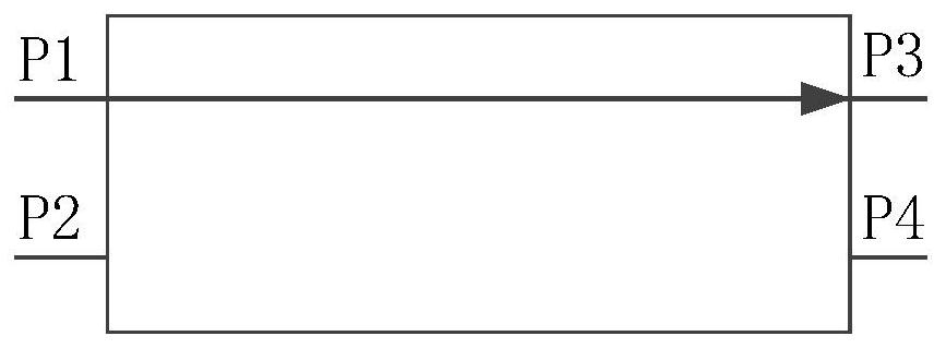
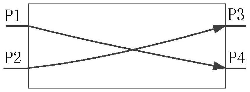
[0039]figure 1 It is a flow chart of an optical switch-based signal transmission method provided by Embodiment 1 of the present invention. This embodiment is applicable to a signal transmission network with multiple connected nodes, and each node is connected to an optical switch. In some cases, the method can be performed by a signal transmission device based on an optical switch, which can be implemented by software and / or hardware, and can be configured in a node of a signal transmission network. The method specifically includes the following steps:
[0040] S101. Send a first enabling signal to the current optical switch, so as to drive the current optical switch to establish a first transmission link.
[0041] In a signal transmission network, a node generally refers to a communication endpoint or a terminal device. A node in a network is an active electronic device connected to the network, capable of sending, receiving or forwarding information through a communication ch...
Embodiment 2
[0062] Figure 5 A schematic structural diagram of an optical switch-based signal transmission device provided in Embodiment 2 of the present invention, the device may specifically include the following modules:
[0063] The signal sending module 501 is configured to send a first enabling signal to the current optical switch to drive the current optical switch to establish a first transmission link, and the first transmission link indicates that the current optical switch receives the previous The first signal transmitted by the optical switch, transmitting the first signal to the current node, receiving the second signal transmitted by the current node, and sending the second signal to the next optical switch, the first The second signal includes the first signal and the current signal generated by the node;
[0064] A detection module 502, configured to detect the current working status of the node;
[0065]An exception processing module 503, configured to send a second en...
Embodiment 3
[0078] Figure 6 A schematic structural diagram of a computer device provided in Embodiment 3 of the present invention, such as Figure 6 As shown, the computer device includes a processor 600, a memory 601, a communication module 602, an input device 603 and an output device 604; the number of processors 600 in the computer device may be one or more, Figure 6 Take a processor 600 as an example; the processor 600, memory 601, communication module 602, input device 603 and output device 604 in the computer equipment can be connected by bus or other methods, Figure 6 Take connection via bus as an example.
[0079] The memory 601, as a computer-readable storage medium, can be used to store software programs, computer-executable programs, and modules, such as the modules corresponding to the optical switch-based signal transmission method in the embodiment of the present invention (for example, the optical switch-based signal transmission method The signal sending module 501, ...
PUM
 Abstract
Description
Claims
Application Information
 - R&D
- Intellectual Property
- Life Sciences
- Materials
- Tech Scout
- Unparalleled Data Quality
- Higher Quality Content
- 60% Fewer Hallucinations
Browse by: Latest US Patents, China's latest patents, Technical Efficacy Thesaurus, Application Domain, Technology Topic, Popular Technical Reports.
© 2025 PatSnap. All rights reserved.Legal|Privacy policy|Modern Slavery Act Transparency Statement|Sitemap|About US| Contact US: help@patsnap.com


