Anti-collision transfer support for intensive care of patients
A transfer frame and patient technology, applied in the field of medical equipment, can solve the problems of inability to adjust the length of the transfer frame and inconvenient use, and achieve the effect of eliminating potential safety hazards and reducing shock
- Summary
- Abstract
- Description
- Claims
- Application Information
AI Technical Summary
Problems solved by technology
Method used
Image

Examples
Embodiment 1
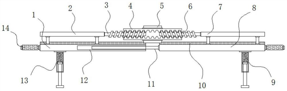
[0026] Example 1: See Figure 1-4 , an anti-bruising patient transfer frame for intensive care, comprising a first support plate 1 and a second support plate 8, the front and rear ends of the top of the first support plate 1 are respectively fixedly connected with the first fixing rod 2, and the second support plate The front and rear ends of the top of the plate 8 are respectively fixedly connected with the second fixed rod 7, the front and rear ends of the first support plate 1 and the second support plate 8 are respectively fixedly connected with handles 14, the first support plate 1 and the second support plate The top of the plate 8 is provided with a protective pad 10, the front and rear ends of the first support plate 1 and the bottom of the second support plate 8 are respectively fixedly connected with legs 13, the inside of the legs 13 is provided with a shock absorbing structure 9, the first support plate 1 and A length adjustment structure is arranged between the se...
Embodiment 2
[0031] Embodiment 2: The shock-absorbing structure 9 is made up of telescopic chamber 901, buffer spring 902, connection block 903 and telescopic rod 904, and telescopic chamber 901 is arranged in the inside of support foot 13, and the top inside telescopic chamber 901 is fixedly connected with buffer spring 902, buffers The bottom end of the spring 902 is fixedly connected with a connection block 903, and the bottom end of the connection block 903 is fixedly connected with a telescopic rod 904;
[0032] The telescopic rod 904 runs through to the bottom end of the leg 13, and the bottom end of the telescopic rod 904 is fixedly connected with a limit block;
[0033] The diameter of the connection block 903 is larger than the diameter of the telescopic rod 904, and a sliding connection is formed between the connection block 903 and the telescopic cavity 901;
[0034] Specifically, such as figure 1 and Figure 4 As shown, when the transfer rack is put down, under the action of ...
Embodiment 3
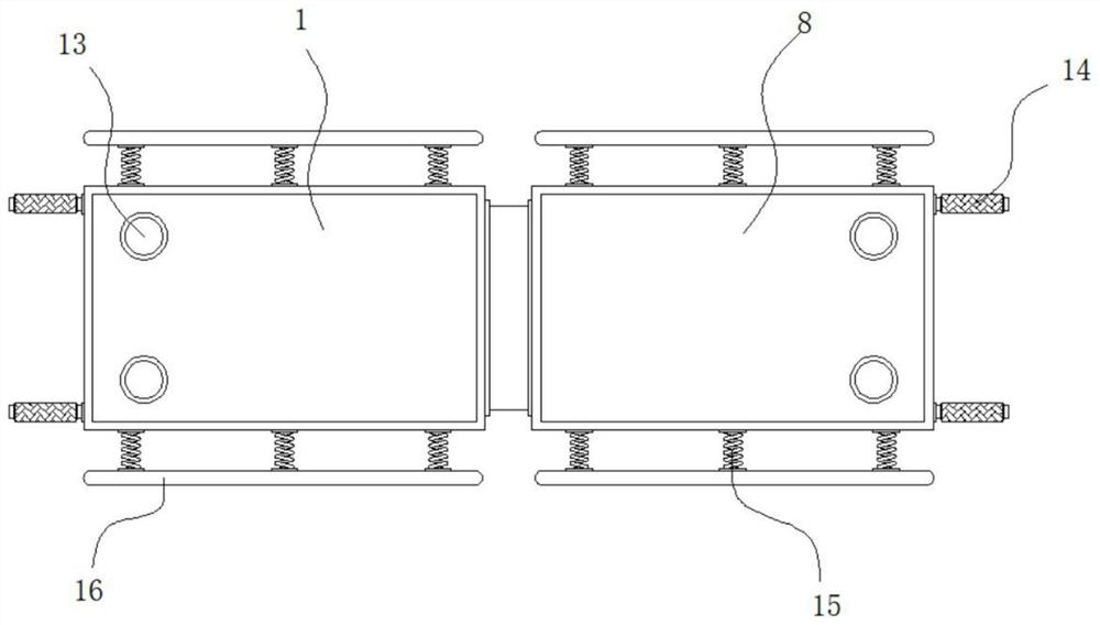
[0035] Embodiment 3: The front and rear ends of the first support plate 1 and the second support plate 8 are fixedly connected with multiple groups of anti-collision springs 15, and one end of the anti-collision springs 15 is fixedly connected with an anti-collision plate 16;
[0036] Specifically, such as figure 1 and image 3 As shown, when in use, the anti-collision spring 15 can make the anti-collision plate 16 have a certain buffer protection effect, so that both sides of the first support plate 1 and the second support plate 8 can have a certain anti-collision function, preventing the second The two sides of the first support plate 1 and the second support plate 8 accidentally collide, eliminating the potential safety hazard of the transfer frame.
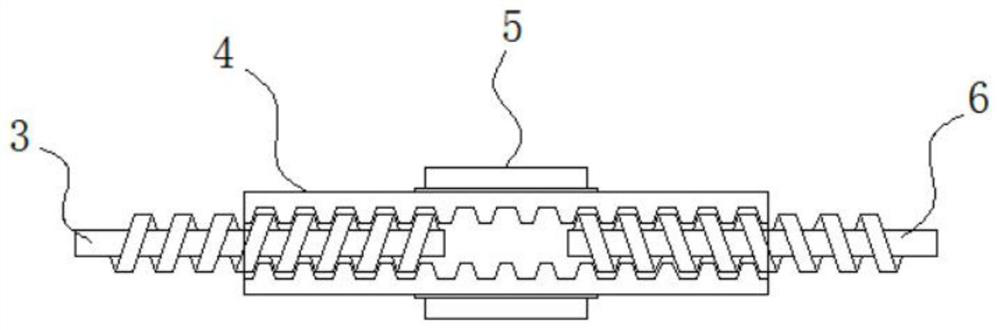
[0037]Working principle: when the present invention is in use, firstly, when the length of the transfer frame needs to be adjusted according to the height of the patient, the hexagonal bolt 5 is turned, and the hexagonal bol...
PUM
 Abstract
Description
Claims
Application Information
 - R&D
- Intellectual Property
- Life Sciences
- Materials
- Tech Scout
- Unparalleled Data Quality
- Higher Quality Content
- 60% Fewer Hallucinations
Browse by: Latest US Patents, China's latest patents, Technical Efficacy Thesaurus, Application Domain, Technology Topic, Popular Technical Reports.
© 2025 PatSnap. All rights reserved.Legal|Privacy policy|Modern Slavery Act Transparency Statement|Sitemap|About US| Contact US: help@patsnap.com