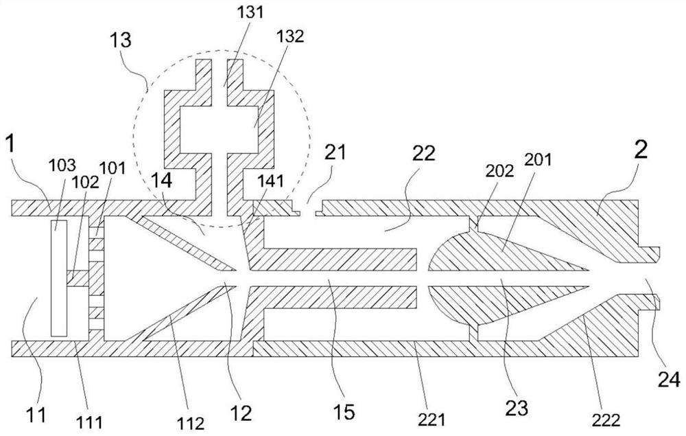
A two-stage cavitation bubble generator

A technology of cavitation bubbles and generators, applied in chemical instruments and methods, fluid mixers, chemical/physical processes, etc., can solve the problems of low cavitation efficiency and poor cavitation dissociation effect of cavitation bubble generators

Active Publication Date: 2021-11-05
CENT SOUTH UNIV
View PDF23 Cites 0 Cited by
  • Summary
  • Abstract
  • Description
  • Claims
  • Application Information

AI Technical Summary

Problems solved by technology

[0006] The invention provides a two-stage cavitation bubble generator to solve the problems of low cavitation efficiency and poor cavitation dissociation effect of the cavitation bubble generator in the related art

Method used


Image

  • A two-stage cavitation bubble generator
  • A two-stage cavitation bubble generator
  • A two-stage cavitation bubble generator

Examples


Embodiment Construction

[0039] In order to make the purpose, technical solution and advantages of the present invention clearer, the technical solution of the present invention will be described in detail below. Apparently, the described embodiments are only some of the embodiments of the present invention, but not all of them. Based on the embodiments of the present invention, all other implementations obtained by persons of ordinary skill in the art without making creative efforts fall within the protection scope of the present invention.

[0040] In describing the present invention, it should be understood that the terms "upper", "lower", "front", "rear", "left", "right", "top", "bottom", "inner", " The orientation or positional relationship indicated by "outside", "center", "longitudinal", "horizontal", "vertical", "horizontal", etc. is based on the orientation or positional relationship shown in the drawings, and is only for the convenience of describing the present invention and Simplified des...


PUM


Abstract

The invention discloses a two-stage cavitation bubble generator, comprising: a first cavitation section, which includes a first jet chamber, a compression channel, an air cavity, and a mixing channel; the first jet chamber, a compression channel, an air chamber, The mixing channel communicates in sequence along the fluid flow direction; the second cavitation section, which includes a second jet chamber with an open end, an outlet channel for outputting fluid, and a central body; the open end of the second jet chamber is connected to the fluid in the first cavitation section The output end is connected, and the other end of the second jet chamber communicates with the outlet channel; the wall of the second jet chamber is provided with a low-pressure fluid inlet communicating with it; the center body is arranged in the middle of the second jet chamber and is fixedly connected with it, and the center body The radial center is provided with a center body channel for mixing fluid and gas. The cavitation bubble generator has high cavitation efficiency, and a single generator has a wide range of cavitation effects, which can be effectively used in the dissociation process of high-sulfur slag, improve the separation effect of slag-sulfur, and provide a good solution for subsequent flotation sulfur extraction. Base.

Description

technical field [0001] The invention relates to the field of heavy metal metallurgy, in particular to a two-stage cavitation bubble generator. Background technique [0002] The direct leaching process realizes the full wet treatment of zinc sulfide concentrate. The zinc production capacity of the direct leaching process of zinc concentrate in my country is about 500,000 tons / year, and the total amount of high-sulfur slag produced along with it reaches 600,000 tons / year. In addition to elemental sulfur, high-sulfur slag also contains valuable components such as zinc, lead, silver, indium, and toxic elements such as arsenic, cadmium, and mercury. The efficient recovery of elemental sulfur from acid leaching slag embodies the advantages of direct leaching technology. It is also beneficial to the comprehensive recovery of valuable components in the subsequent acid leaching residue. At present, domestic zinc direct leaching enterprises generally adopt the "flotation-hot filtrati...

Claims


Application Information

Patent Timeline
Patent Type & Authority Patents(China)
IPC IPC(8): B01F5/04B01F5/06B01F3/04
CPCB01F23/2319B01F23/2366B01F25/3121B01F25/312B01F25/431B01F25/45
Inventor 张红亮陈千陈永明于心岩李家琦
Owner CENT SOUTH UNIV
Why Eureka
Try Eureka