Automatic cap feeding device for cap screwing operation

An automatic and cap-feeding technology, which is applied in the directions of capping containers tightly with caps, application, packaging, etc., can solve the problems of unsuitable promotion and use, low production efficiency, and low practicability, so as to facilitate promotion and use and improve production Efficiency and the effect of improving practicality

Active Publication Date: 2020-12-04
东莞市新锋机械设备有限公司
View PDF14 Cites 1 Cited by
  • Summary
  • Abstract
  • Description
  • Claims
  • Application Information

AI Technical Summary

Problems solved by technology

[0003] At present, most of the bottle cap sorting devices on the market use the feature that the center of gravity of the bottle cap and its geometric center do not coincide to sort out irregularly shaped bottle caps such as equal cones, and the upper and lower faces of the cap are of the same size or the cap is thinner. The finishing effect of the bottle caps is poor, and manual auxiliary turning may be required. The actual production efficiency is low, and the opening of the bottle caps sorted by some bottle cap sorting devices does not meet the requirements of the cap screwing process. The practicability is poor and it is not suitable for promotion. And use, it is difficult to adjust the limit position of the bottle cap after conveying and sorting, resulting in deviation or falling off when the capping machine is capping, which has a serious impact on the entire packaging process, and this type of device also has complex structures and maintenance Difficult problem, the bottle cap is easy to get stuck in the machine parts during the sorting or conveying process, causing device failure and damage, and the practicability is low

Method used


Image

  • Automatic cap feeding device for cap screwing operation
  • Automatic cap feeding device for cap screwing operation
  • Automatic cap feeding device for cap screwing operation

Examples


Embodiment Construction

[0027] The following will clearly and completely describe the technical solutions in the embodiments of the present invention with reference to the accompanying drawings in the embodiments of the present invention. Obviously, the described embodiments are only some, not all, embodiments of the present invention. Based on the embodiments of the present invention, all other embodiments obtained by persons of ordinary skill in the art without making creative efforts belong to the protection scope of the present invention.

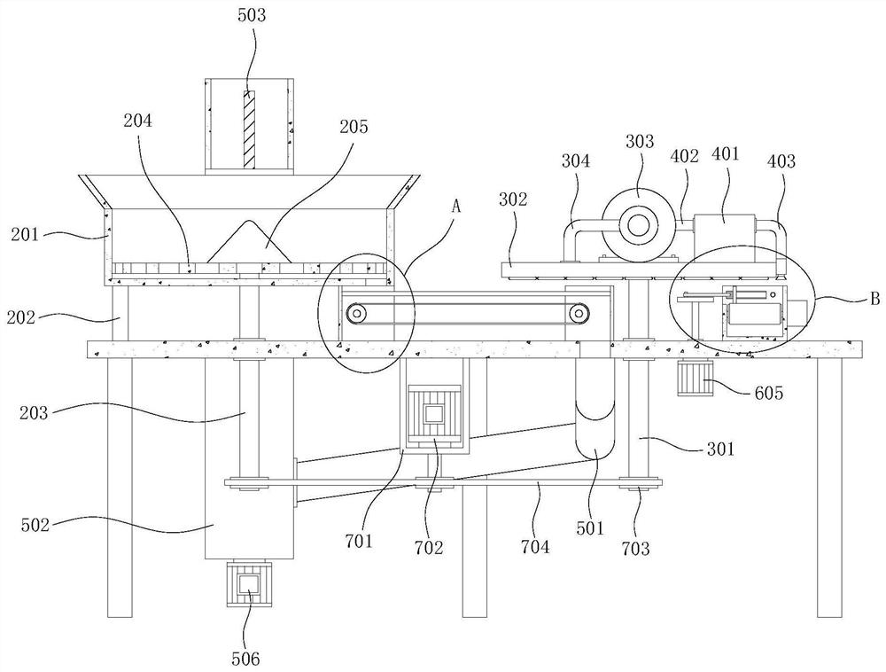
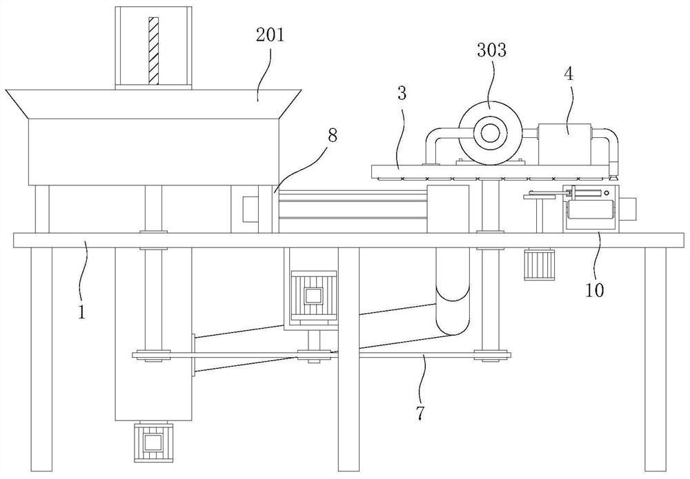
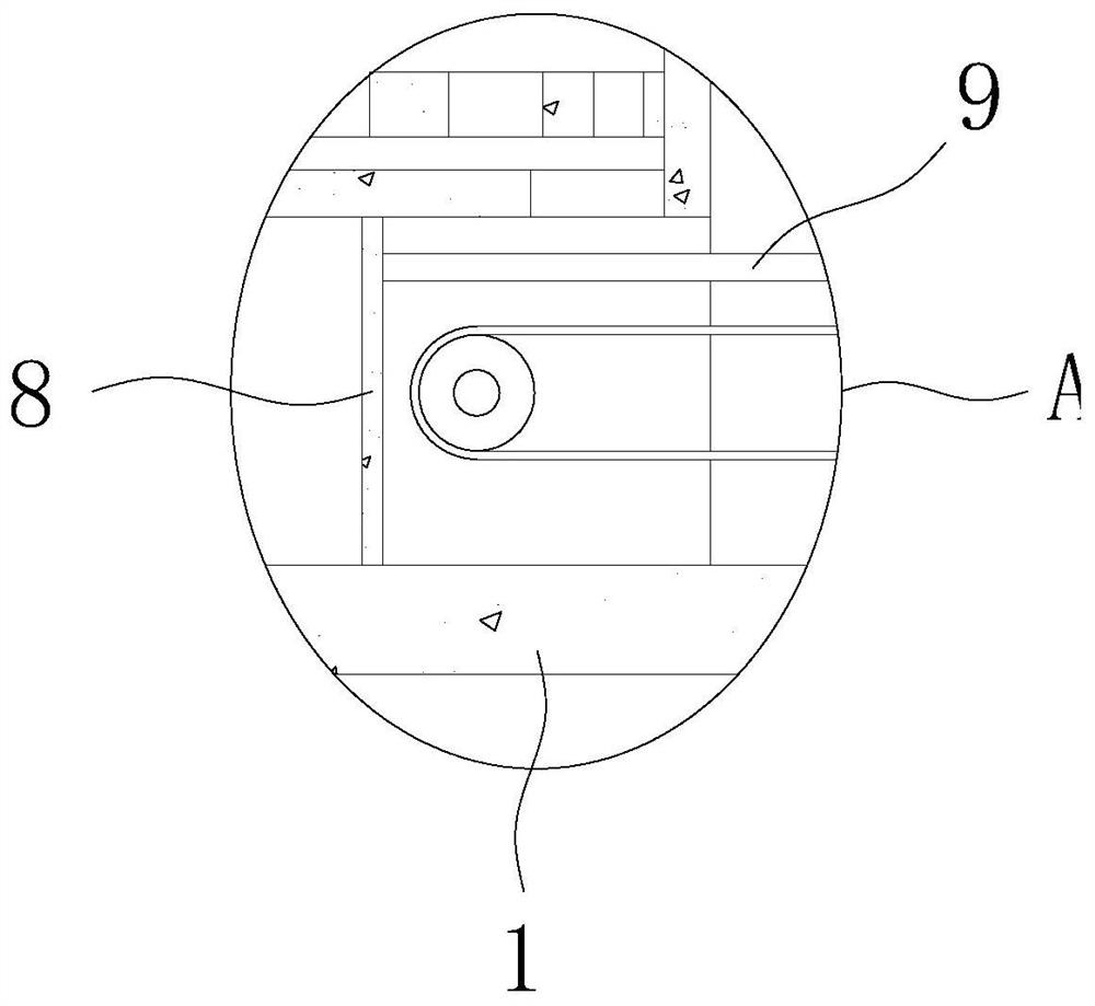
[0028] see Figure 1-8, the present invention provides a technical solution: an automatic cap feeding device for capping operations, including a workbench 1, the bottom outer surface of the workbench 1 is welded with six sets of support legs, and the workbench 1 is provided with a sorting Mechanism 2, screening and feeding mechanism 3, dust removal mechanism 4, recovery mechanism 5, pushing material alignment mechanism 6 and transmission mechanism 7, two sets ...


PUM


Abstract

The invention discloses an automatic cap feeding device for cap screwing operation, and relates to the technical field of packaging equipment. The automatic cap feeding device for the cap screwing operation comprises a workbench, wherein six supporting legs are welded and mounted on the outer surface of the bottom of the workbench; a sorting mechanism, a screening and feeding mechanism, a dust removing mechanism, a recycling mechanism, a pushing and alignment mechanism and a transmission mechanism are arranged on the workbench; two mounting frames are welded and mounted on the outer surface ofthe top of the workbench and distributed symmetrically; and two limiting rods are welded and mounted on the inner walls of the two mounting frames. According to the automatic cap feeding device for the cap screwing operation, the use scene and range of the device are wider, the use and the popularization of the device are facilitated, and it is guaranteed that the openings of arranged bottle capsall face downwards, so that compared with a part of devices with the openings of arranged bottle caps facing upwards, the practicability of the automatic cap feeding device is higher, the cap screwing operation requirement of most cap screwing machines in the market is met, the convenience is provided for subsequent processes, and the production efficiency of the whole packaging process is further improved.

Description

technical field [0001] The invention relates to the technical field of packaging equipment, in particular to an automatic cap feeding device for cap screwing operations. Background technique [0002] Capping operation is an indispensable step in the bottle packaging process. Simply put, it is to tighten the bottle cap on the bottle mouth. Before this step, the bottle cap needs to be sorted and transported to the capping machine. After sorting It is necessary to ensure that the front and back of the bottle cap are uniform to meet the needs of the capping operation. [0003] At present, most of the bottle cap sorting devices on the market use the feature that the center of gravity of the bottle cap and its geometric center do not coincide to sort out irregularly shaped bottle caps such as equal cones, and the upper and lower faces of the cap are of the same size or the cap is thinner. The finishing effect of the bottle caps is poor, and manual auxiliary turning may be require...

Claims


Application Information

Patent Timeline
Patent Type & Authority Applications(China)
IPC IPC(8): B67B3/00B65G47/256B65G47/91B65G47/82B65G47/22B67B3/20
CPCB67B3/003B65G47/256B65G47/915B65G47/82B65G47/22B67B3/20
Inventor 彭世香
Owner 东莞市新锋机械设备有限公司
Why Eureka
Try Eureka