
Cutting machine capable of compressing periphery

A cutting machine and cutting device technology, applied in the field of cutting machines, can solve the problems of easy movement of fabrics and poor cutting quality, and achieve the effect of accurate and stable fabric position, simple structure, and guaranteed cutting quality

Active Publication Date: 2020-12-04
TAIZHOU ZHONGGANG CHEM & CONSTR CO LTD
View PDF7 Cites 2 Cited by
  • Summary
  • Abstract
  • Description
  • Claims
  • Application Information

AI Technical Summary

Problems solved by technology

[0004] The purpose of the present invention is to solve the technical problem that the fabric of the existing cutting machine is easy to move, resulting in poor cutting quality, and to provide a cutting machine with four-sided compression

Method used


Image

  • Cutting machine capable of compressing periphery

Examples


Embodiment Construction

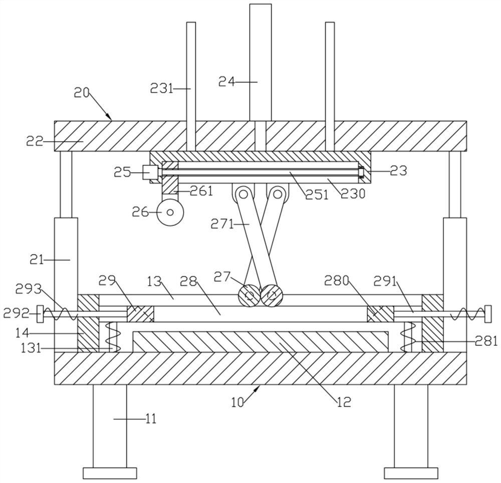
[0014] like figure 1 As shown, a cutting machine that is compressed around includes a workbench 10 and a cutting device 20; the bottom of the workbench 10 is formed with a number of evenly distributed support feet 11, and a cutting table 12 is provided on the upper end surface; the cutting device 20 includes Lifting support plate 22; Lifting support plate 22 lifting is arranged on the top of workbench 10; The bottom surface of lifting support plate 22 is provided with cutting support plate 23; The bottom surface of cutting support plate 23 moves left and right and is provided with cutting mobile seat 261; The bottom of the cutting mobile seat 261 is provided with a cutting round knife 26; the left part and the right end of the lower end surface of the cutting support plate 23 are respectively elastically hinged and provided with a pair of front and back symmetrical swing connecting plates 271; a pair of swing connecting plates 271 on the left side are located at Between the ri...


PUM


Abstract

The invention discloses a cutting machine capable of compressing the periphery. A cutting device comprises a lifting supporting plate. The lifting supporting plate is arranged over a workbench in a lifting manner. A cutting support plate is arranged on the bottom surface of the lifting supporting plate in a lifting manner; a cutting moving seat is arranged on the bottom surface of the cutting support plate in a left-right moving manner; a cutting circular knife is arranged at the bottom of the cutting moving seat; the left and right ends of the lower end surface of the cutting support plate are respectively and elastically hinged with a pair of swing connecting plates which are symmetrically arranged front and back; the pair of swing connecting plates at the left side is located between the pair of swing connecting plates at the right side; cylindrical smoothing rollers are rotationally arranged between the lower ends of the pair of swing connecting plates at the left side and betweenthe lower ends of the pair of swing connecting plates at the right side; and the pair of swing connecting plates at the left side and the pair of swing connecting plates at the right side are arrangedin a crossed manner.

Description

technical field [0001] The invention relates to the technical field of cutting machines, in particular to a cutting machine with pressing around. Background technique [0002] In the production of clothes, it is often necessary to cut the cloth, and when cutting the cloth, a cloth cutting machine will be used. The cloth cutting machine mainly includes a frame, a cutting table and a cutting machine. When in use, lay the cloth on the cutting table, then press down the cutting machine, start the cutting machine, and the cutting machine can move on the frame to cut the cloth. [0003] However, in the prior art, in the process of cutting the cloth, since there are no positioning devices on both sides of the cloth, it is easy to cause the cloth to move, and the size of the cut cloth does not meet the requirements, resulting in lower cutting quality; For soft fabrics such as lace, the fabric is more likely to move, and the cutting quality is very poor. Contents of the invention...

Claims


Application Information

Patent Timeline
Patent Type & Authority Applications(China)
IPC IPC(8): D06H7/00
CPCD06H7/00
Inventor 程祖友
Owner TAIZHOU ZHONGGANG CHEM & CONSTR CO LTD
Learn More