Constant velocity turning joint

A technology of constant velocity universal joints and external joints, which is applied to rotating parts, elastic couplings, and mechanical equipment that resist centrifugal force, and can solve problems such as shortening service life and reducing breaking strength

Inactive Publication Date: 2003-09-03
GKN LOBRO
View PDF3 Cites 2 Cited by
  • Summary
  • Abstract
  • Description
  • Claims
  • Application Information

AI Technical Summary

Problems solved by technology

[0004] For prior art joint designs, on the one hand, any improvement such as with respect to the articulation angle can only be achieved by shortening the service life and reducing the breaking strength

Method used


Image

  • Constant velocity turning joint
  • Constant velocity turning joint
  • Constant velocity turning joint

Examples


Embodiment Construction

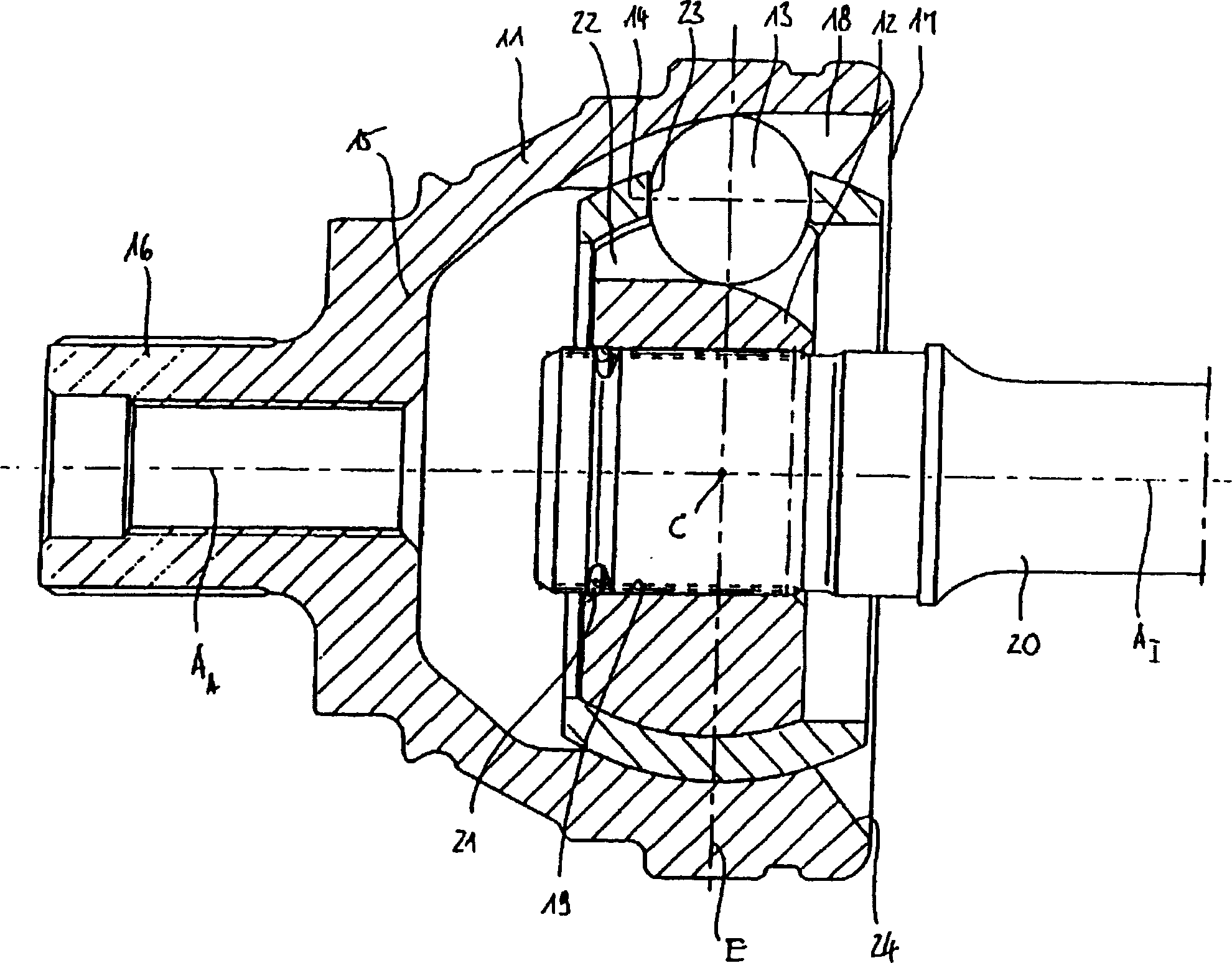
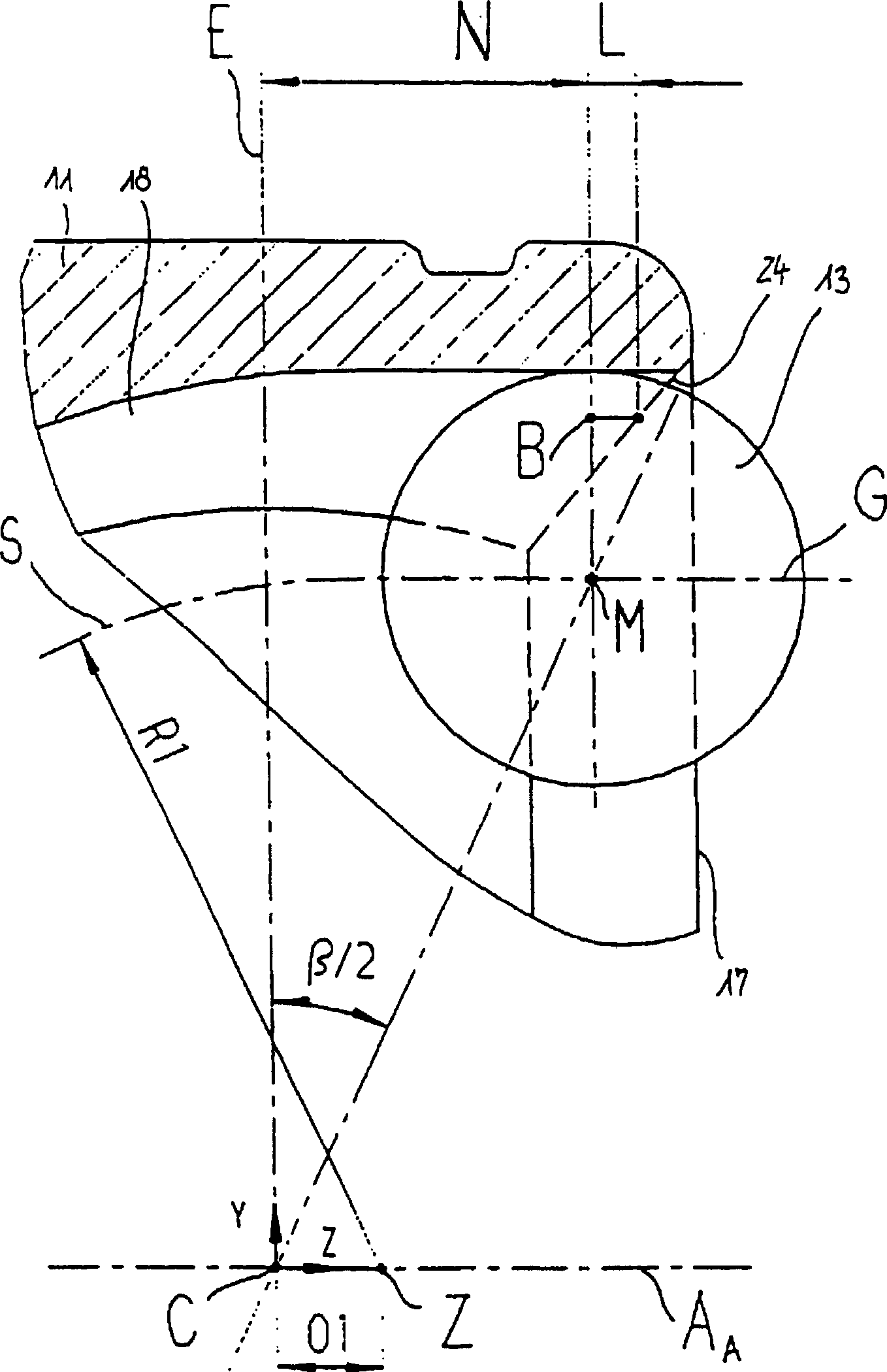
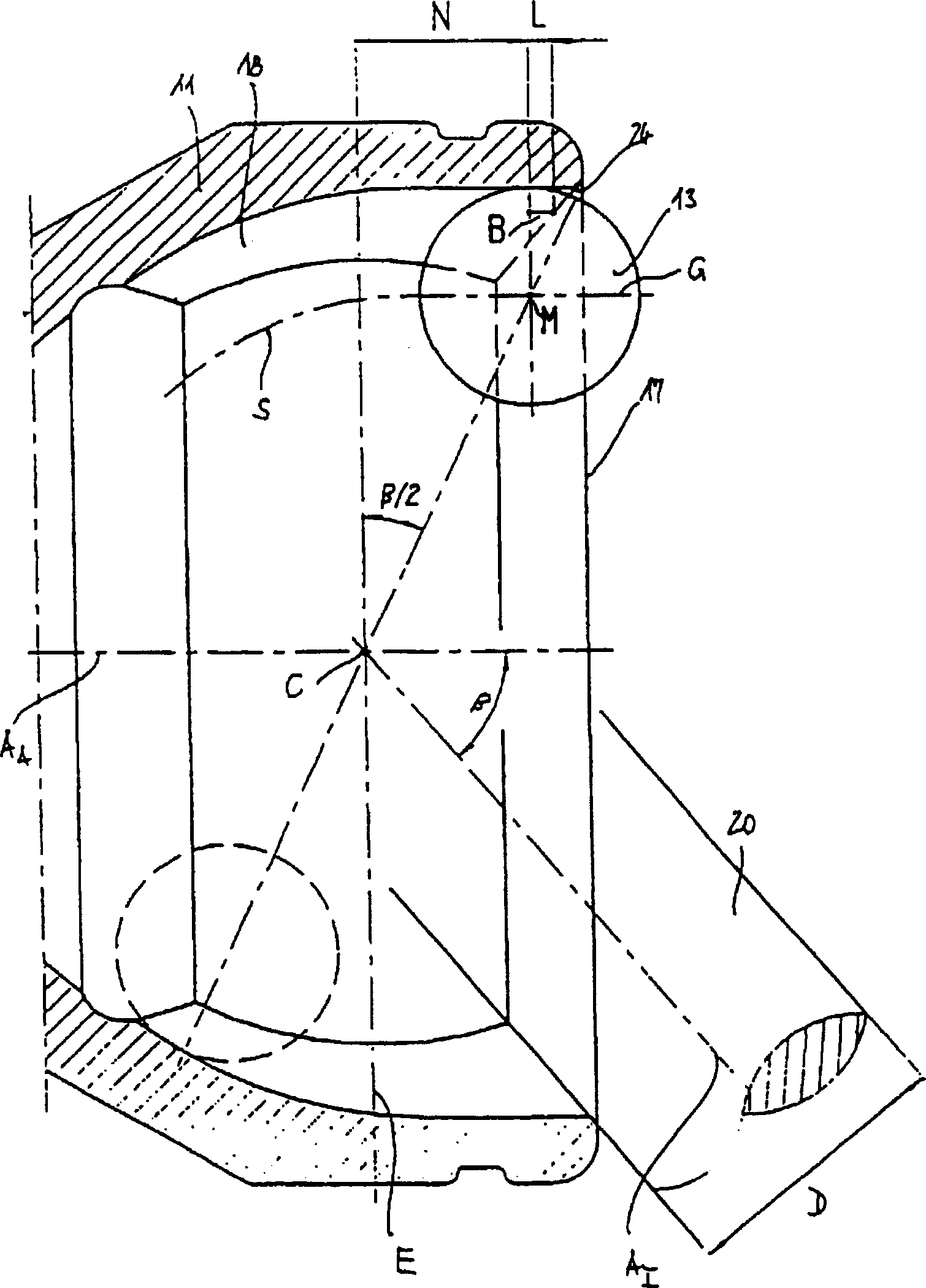
[0019] figure 1 There is shown a prior art constant velocity universal joint comprising an outer joint part 11, an inner joint part 12, torque transmitting balls 13 and a ball spacer 14. At one end, the outer joint part 11 is closed off by a bottom 15 followed by a joint journal 16 . Opposite the bottom 15 in the axial direction is a bore 17 of the outer joint part 11 . In the outer joint part 11, one of a plurality of outer ball tracks 18 distributed along the outer circumference is shown, as viewed from the open end 17, this track is not undercut. The inner joint part 12 is provided with a central hole 19 through which a connecting shaft 20 fixed axially by a positioning ring 21 is inserted. In this inner joint part 12, one of a plurality of outer ball tracks 22 distributed along the outer circumference is shown, which track is also free of undercuts as seen from the open end 17. The outer ball track 18 and the inner ball track 22 are associated with each other as a pair ...


PUM


Abstract

A constant velocity universal joint for transmitting torque, having an outer joint part with outer ball tracks, an inner joint part with inner ball tracks, torque transmitting balls guided by pairs of outer and inner ball tracks positioned in corresponding meridian planes, and a ball cage which receives the balls in circumferentially distributed windows and holds same in a common plane and guides same on to the angle-bisecting plane when the joint is ariculated, with the center lines of the outer and inner ball tracks being composed of at least two differently curved portions adjoining one another, with the center lines of the ball tracks of the outer joint part each comprising convexly curved inner portions and, towards the open end, concavely curved end portions.

Description

technical field [0001] The present invention relates to a constant velocity universal joint for torque transmission, which has: an outer joint part with outer ball tracks; Outer and inner ball track guides in the meridian plane of ; and, a ball spacer that accommodates the balls in windows distributed along the outer circle and keeps the balls in a common plane and when The balls are guided on the angle bisector when hinged to the joint, and the centerlines of the outer and inner ball tracks consist of at least two distinctly curved sections joined to each other. Background technique [0002] Such joints are known as Rzeppa fixed joints (RF) or uncut fixed joints (UF). The latter is described in German patent RE-PS 22 52 827 . For a certain size of such joints, and especially with respect to the axial length of these joints, there is a mutual dependence between the maximum articulation angle and the thickness of the shaft to be connected with the inner joint part. On the ...

Claims


Application Information

Patent Timeline
IPC IPC(8): F16D3/223F16D3/2233F16D3/2237
CPCF16D3/2233F16D2003/22306Y10S464/906F16D3/2237F16D3/223
Inventor 彼得·施瓦茨勒弗里德海尔姆·约翰
Owner GKN LOBRO
Why Eureka
Try Eureka