
Drainage pipe network monitoring system

A monitoring system and drainage pipe network technology, which can be used in pipeline systems, waterway systems, and sewage removal, etc., can solve the problems of lack of drainage flow and inability to monitor the flow direction, and achieve reliable connection, low implementation cost, and convenient inspection and maintenance. Effect

Inactive Publication Date: 2020-12-04
吴开文
View PDF0 Cites 0 Cited by
  • Summary
  • Abstract
  • Description
  • Claims
  • Application Information

AI Technical Summary

Problems solved by technology

[0004] The purpose of the present invention is to provide a drainage pipe network monitoring system to solve the technical problems in the prior art that do not have the ability to monitor drainage flow and flow direction, and cannot realize the recovery of drainage kinetic energy and the purification of solid impurities.

Method used


Image

  • Drainage pipe network monitoring system
  • Drainage pipe network monitoring system
  • Drainage pipe network monitoring system

Examples


Embodiment Construction

[0029] Below in conjunction with accompanying drawing, the present invention is described in detail:

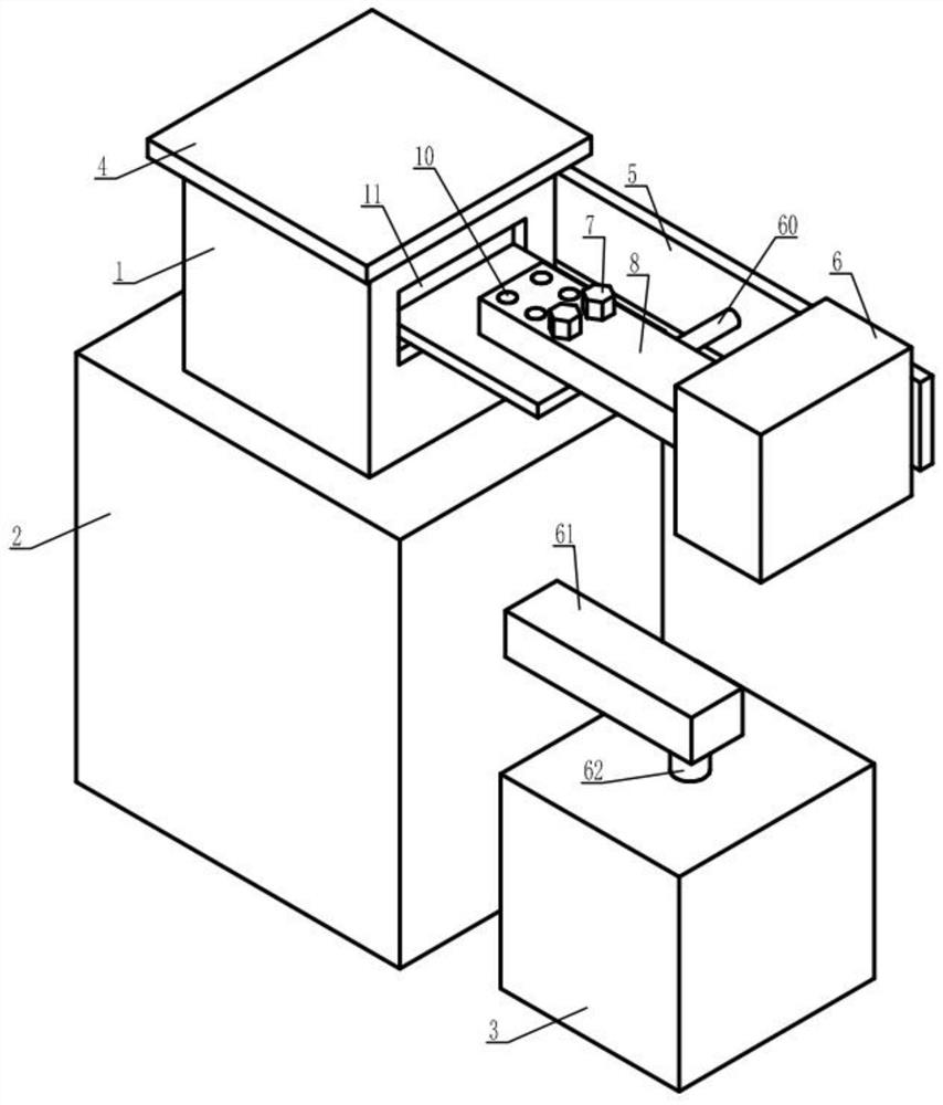
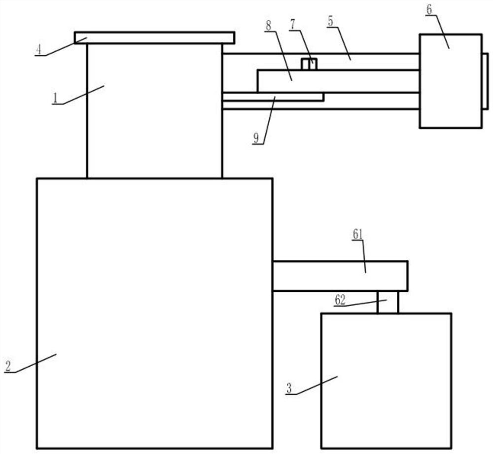
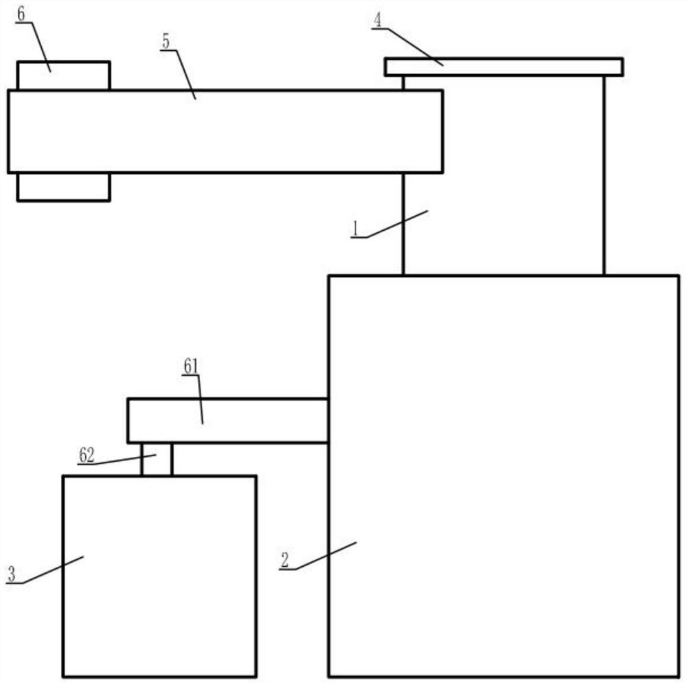
[0030] see Figure 1 to Figure 9 , a drainage pipe network monitoring system provided by the present invention includes a monitoring room 1, the bottom end of the monitoring room 1 is provided with an energy storage room 2, the right side of the energy storage room 2 and the side pipe 61 The left end of the side pipe 61 is communicated with the top end of the communication circular pipe 62, the bottom end of the communication circular pipe 62 is communicated with the upper surface of the clean room 3, and the top of the monitoring room 1 is provided with There is a top plate 4, a side window 11 is provided on the right side of the monitoring room 1, and an upper fixing block 14 and a lower fixing block 17 are fixed on the inner right surface of the monitoring room 1 by welding. The upper fixing block The lower end of 14 is connected with the top end of the upper sealing plat...


PUM


Abstract

The invention provides a drainage pipe network monitoring system. The drainage pipe network monitoring system comprises a monitoring room, wherein an energy storage room is arranged at the bottom endof the monitoring room; the right side surface of the energy storage room communicates with the left end of a side square pipe; the right end of the side square pipe communicates with the top end of acommunicating circular pipe; the bottom end of the communicating circular pipe communicates with the upper surface of a purifying room; a top plate is arranged at the top of the monitoring room; a side window is arranged on the right side surface of the monitoring room; an upper fixing block and a lower fixing block are fixed to the right surface of the interior of the monitoring room in a welding manner; the lower end of the upper fixing block is connected with the top end of an upper sealing plate through an upper compression spring; the bottom end of the upper sealing plate is in contact with the upper surface of a spoiler; the upper end of the lower fixing block is connected with the bottom end of a lower sealing plate through a lower compression spring; and the top end of the lower sealing plate is in contact with the lower surface of the spoiler. According to the technical scheme disclosed by the invention, the technical problems that in the prior art, the drainage flow rate andthe flow direction monitoring capacity are not achieved, and drainage kinetic energy recovery, solid impurity purification and the like cannot be realized are effectively solved, and popularization and application are facilitated.

Description

technical field [0001] The invention relates to the technical field of drainage equipment, in particular, to a drainage pipe network monitoring system. Background technique [0002] With the acceleration of urbanization in my country, a large number of new pipe networks and water pipes are running through water every year. There are a large number of drainage equipment in the city, forming a corresponding urban drainage system. At present, the urban drainage pipe network has the characteristics of huge structure and complex structure. The mode, intelligence level, and accuracy rate cannot meet the needs of the existing technology. Drainage pipe network is the backbone of urban water pollution prevention and control and urban waterlogging and waterlogging drainage. It is very important to real-time monitoring and early warning of the drainage pipe network and to improve the management and protection efficiency of the drainage pipe network. [0003] The invention of the drai...

Claims


Application Information

Patent Timeline
Patent Type & Authority Applications(China)
IPC IPC(8): E03F1/00E03F5/00E03F5/14G08B21/24G08B3/10F17D5/00
CPCE03F1/00E03F5/00E03F5/14E03F2201/20F17D5/00G08B3/10G08B21/24
Inventor 吴开文
Owner 吴开文
Learn More