Underground fluid identification device based on distributed optical fiber sensing technology and measurement method

A technology of distributed optical fiber and sensing technology, applied in the field of distributed optical fiber sensing, can solve the problems of complex structure of downhole sensors or probes, low reliability and accuracy, difficult and cumbersome installation process, etc.

Pending Publication Date: 2020-12-04
OPTICAL SCI & TECH (CHENGDU) LTD
View PDF0 Cites 5 Cited by
  • Summary
  • Abstract
  • Description
  • Claims
  • Application Information

AI Technical Summary

Problems solved by technology

Most of the above-mentioned downhole fluid identification methods, devices or systems have complex structures of downhole sensors or probes, difficult and cumbersome installation process, low reliability and accuracy, and it is difficult to realize full well detection without affecting the normal production of oil and gas wells. On-line real-time measurement or monitoring of downhole fluid

Method used


Image

  • Underground fluid identification device based on distributed optical fiber sensing technology and measurement method
  • Underground fluid identification device based on distributed optical fiber sensing technology and measurement method
  • Underground fluid identification device based on distributed optical fiber sensing technology and measurement method

Examples


Embodiment Construction

[0036] Embodiments of the present invention will be described in detail below in conjunction with the accompanying drawings, but they are not intended to limit the present invention, but are merely examples, and at the same time, the advantages of the present invention will become clearer and easier to understand.

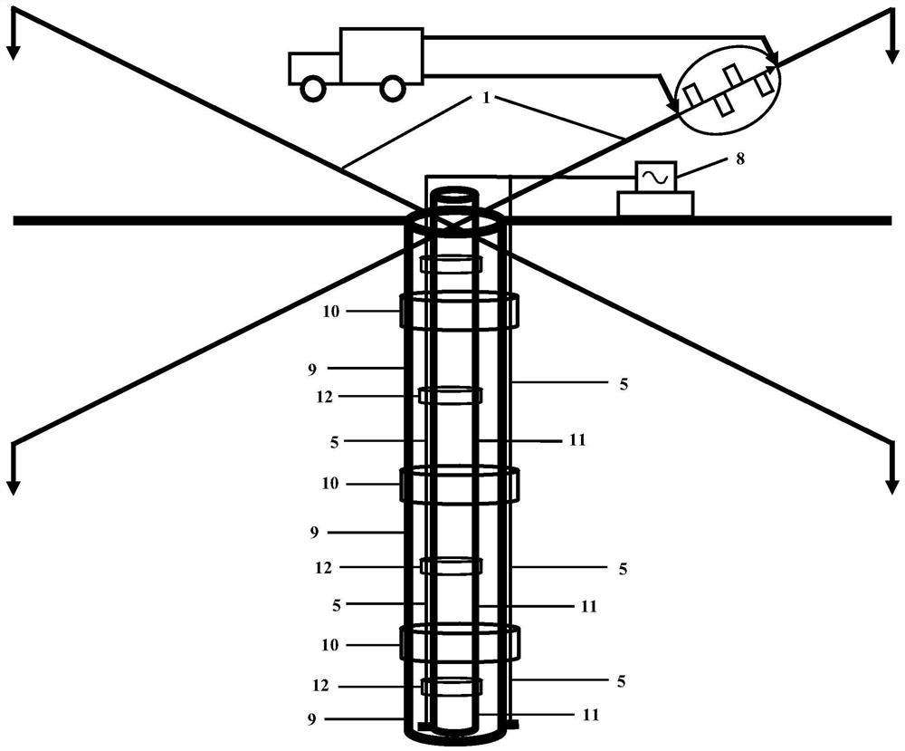
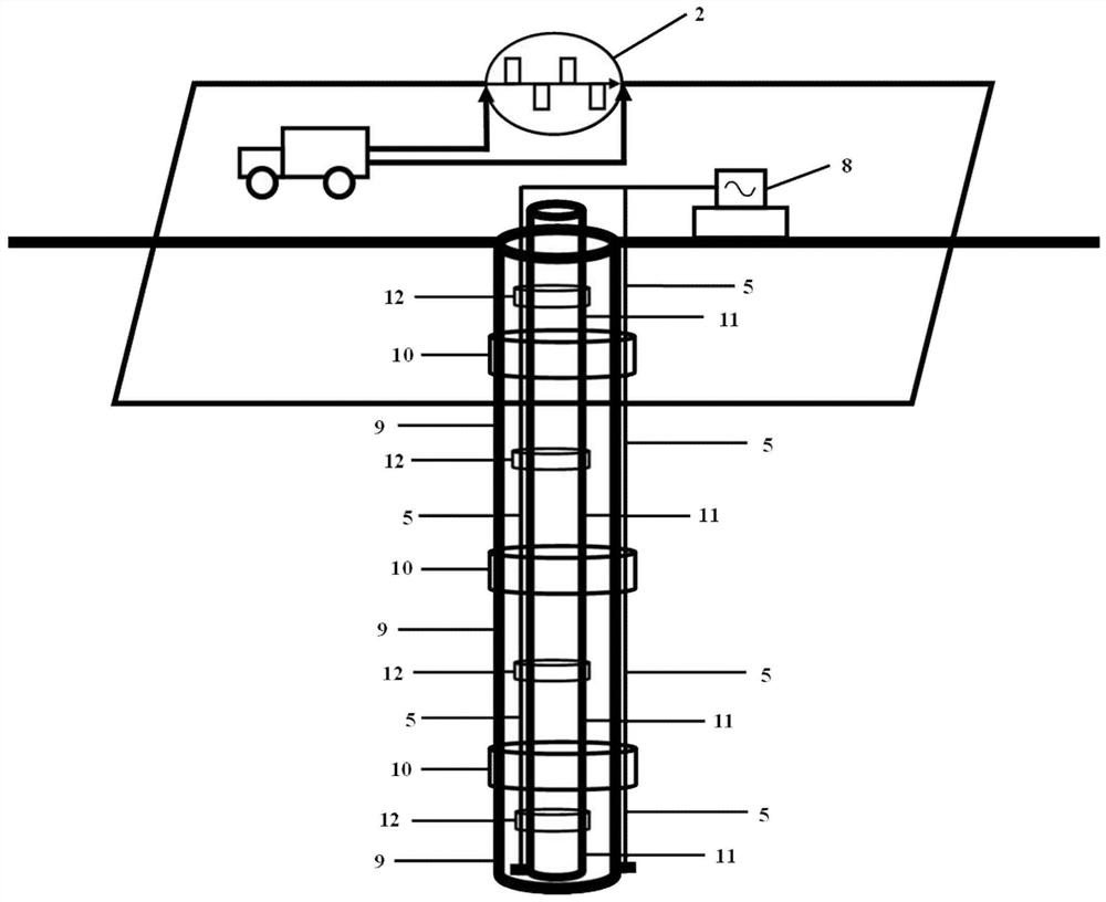
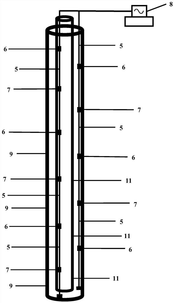
[0037] Such as figure 1 or figure 2As shown, the downhole fluid identification device based on distributed optical fiber sensing technology includes a ground high-power electromagnetic excitation source, an armored optical cable 5, and the armored optical cable 5 is laid outside the metal casing 9 or inside the metal casing 9 or It is fixed outside the oil pipe 11 or inside the oil pipe 11; the three-component optical fiber electric field sensor 6 and the three-component optical fiber magnetic field sensor 7 are evenly distributed in the armored optical cable 5; the armored optical cable 5 is connected to the composite modulation and demodulation instrument 8 on t...


PUM


Abstract

The invention provides an underground fluid identification device based on a distributed optical fiber sensing technology and a measurement method. The underground fluid identification device comprises a ground high-power electromagnetic excitation source and an armored optical cable, and the armored optical cable is arranged outside or inside a metal sleeve or fixed outside or inside an oil pipe;three-component optical fiber electric field sensors and three-component optical fiber magnetic field sensors are uniformly distributed in the armored optical cable; and the armored optical cable isconnected with a composite modulation-demodulation instrument on the ground. The ground high-power electromagnetic excitation source continuously excites forward and reverse square wave source signalswith the duty ratio of 1 to the underground, and the proportion of water, oil and gas in multi-phase fluid at each measuring point position is determined according to the actually measured true resistivity value of the fluid inside and outside the metal sleeve or inside and outside the oil pipe; and online real-time measurement, identification and long-term dynamic monitoring of change rules of underground fluid in the development and production process of an oil and gas production well or a liquid injection displacement well are achieved.

Description

technical field [0001] The invention belongs to the technical field of distributed optical fiber sensing, and in particular relates to a downhole fluid identification device and measurement method based on distributed optical fiber sensing technology. Background technique [0002] Optical fiber sensing technology began in 1977 and developed rapidly with the development of optical fiber communication technology. Optical fiber sensing technology is an important symbol to measure the degree of informatization of a country. Optical fiber sensing technology has been widely used in military, national defense, aerospace, industrial and mining enterprises, energy and environmental protection, industrial control, medicine and health, metrology and testing, construction, household appliances and other fields, and has a broad market. There are hundreds of optical fiber sensing technologies in the world, and physical quantities such as temperature, pressure, flow, displacement, vibratio...

Claims


Application Information

Patent Timeline
Patent Type & Authority Applications(China)
IPC IPC(8): E21B47/00E21B47/13E21B49/00
CPCE21B47/00E21B49/00
Inventor 余刚梁兴王熙明安树杰冉曾令张仁志夏淑君
Owner OPTICAL SCI & TECH (CHENGDU) LTD
Why Eureka
Try Eureka