
Adjustable type vibration reducing balance weight device

A counterweight device and adjustable technology, applied in the direction of balance weight, spring/shock absorber, vibration suppression adjustment, etc., can solve the problems of occupying a large space, a large workload of disassembly and assembly, and increasing costs

Pending Publication Date: 2020-12-04
THE GENERAL DESIGNING INST OF HUBEI SPACE TECH ACAD
View PDF0 Cites 1 Cited by
  • Summary
  • Abstract
  • Description
  • Claims
  • Application Information

AI Technical Summary

Problems solved by technology

[0004] However, whether it is to supplement the installation of the vibration damping device or replace the vibration damping device, the mechanical equipment either needs to add an additional installation interface of the vibration damping device, such as lugs, etc.; or it is necessary to add an additional adapter plate to the mechanical equipment that has already fixed the installation interface; For large-scale mechanical equipment, in order to ensure the vibration-reducing performance, a large-scale vibration-reducing device is required, and its corresponding installation interface or adapter plate needs to occupy a large additional space. design plan
At the same time, whether it is to install a new damping device or replace a new damping device, the new damping device needs to be disassembled and tested repeatedly to obtain the required natural frequency, damping, and center of mass position, and usually requires overall disassembly and assembly. The workload of installation is relatively large; and the new vibration damping device will increase additional costs from design to production, and then to processing and installation

Method used


Image

  • Adjustable type vibration reducing balance weight device
  • Adjustable type vibration reducing balance weight device
  • Adjustable type vibration reducing balance weight device

Examples


Embodiment Construction

[0028] In order to make the purposes, technical solutions and advantages of the embodiments of the present application clearer, the technical solutions in the embodiments of the present application will be clearly and completely described below in conjunction with the drawings in the embodiments of the present application. Obviously, the described embodiments It is a part of the embodiments of this application, but not all of them. Based on the embodiments in the present application, all other embodiments obtained by persons of ordinary skill in the art without making creative efforts belong to the protection scope of the present application.

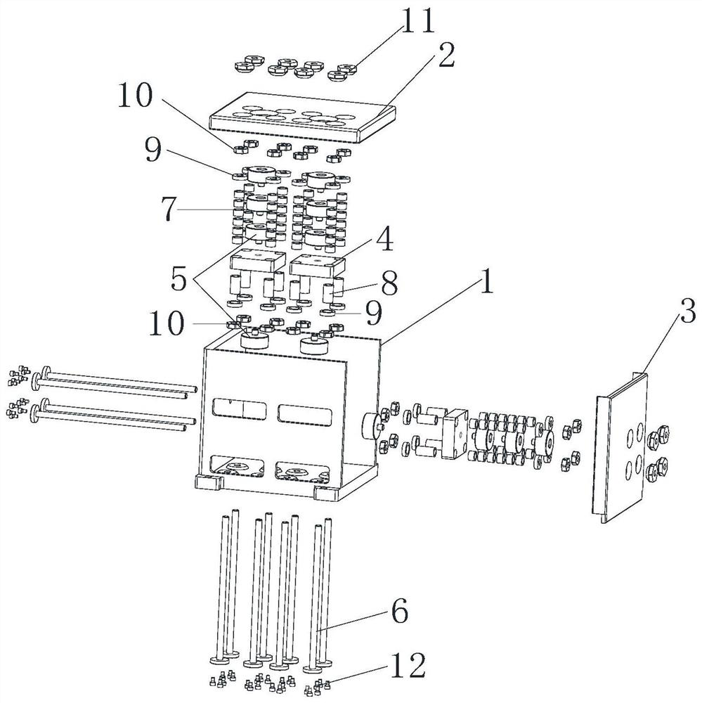
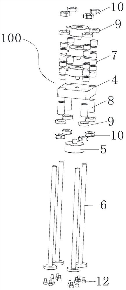
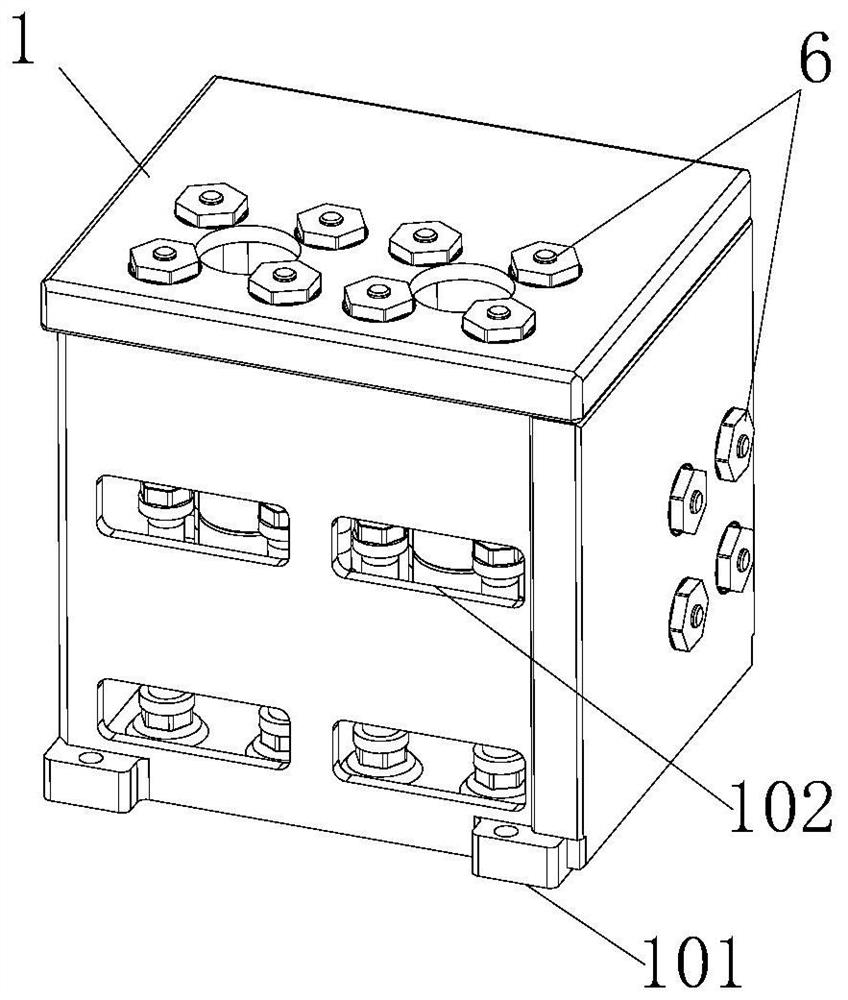
[0029] like figure 1 As shown, the present application discloses an embodiment of an adjustable vibration-absorbing counterweight device. The vibration-absorbing counterweight device is installed on mechanical equipment, which includes a housing 1 and several adjustment modules 100; the housing 1 includes a detachable top Cover 2 and s...


PUM


Abstract

The invention relates to an adjustable type vibration reducing balance weight device and relates to the technical field of mechanical engineering. The adjustable type vibration reducing balance weightdevice is installed on mechanical equipment. A shell comprises a top cover and a side cover. Some of a plurality of adjusting modules are arranged vertically, and the other adjusting modules are arranged transversely. Each adjusting module comprises multiple supporting rods and multiple weights arranged in a stacked manner. Each supporting rod is provided with multiple first vibration reducing pads in a sleeved manner. When a mass center position, fixed frequency and damp need to be changed, the purpose can be achieved by increasing and reducing the number of the weights in the plurality of adjusting modules, changing the positions of the weights in the adjusting modules, increasing and reducing the number of the first vibration reducing pads and replacing types of the first vibration reducing pads. According to the vibration reducing balance weight device, the fixed frequency and damp of the vibration reducing balance weight device achieve the state meeting the vibration reducing requirement of the mechanical equipment, and the mass center of the mechanical equipment assembled with the vibration reducing balance weight device reaches the state meeting the use requirement of the mechanical equipment.

Description

technical field [0001] The present application relates to the technical field of mechanical engineering, in particular to an adjustable vibration-absorbing counterweight device. Background technique [0002] For some mechanical equipment, in some special working conditions, the mechanical equipment will face the resonance problem caused by external excitation, and the resonance will cause the damage of the mechanical equipment or the loss of the precision of the mechanical equipment, and the resonance is mainly determined by the natural frequency and damping of the mechanical equipment . At the same time, based on the specific mechanical equipment, the position of the center of mass is not at the geometric center of the installation interface, which will directly cause the mechanical equipment to face the problem of line-angle coupling during motion. Based on the specific rotating mechanical equipment, the position of the center of mass is not on the rotating axis, which wi...

Claims


Application Information

Patent Timeline
Patent Type & Authority Applications(China)
IPC IPC(8): F16F15/28
CPCF16F15/286
Inventor 邱东熊朝兵李旦
Owner THE GENERAL DESIGNING INST OF HUBEI SPACE TECH ACAD
Learn More