Vapor chamber and manufacturing method for the same

一种制造方法、均温板的技术,应用在热传导领域,能够解决困难等问题,达到增加冷却表面面积、避免变形或泄漏、提升回流速度的效果

Active Publication Date: 2020-12-04
COOLER MASTER CO LTD
View PDF8 Cites 1 Cited by
  • Summary
  • Abstract
  • Description
  • Claims
  • Application Information

AI Technical Summary

Problems solved by technology

[0004] Generally speaking, the vapor chamber utilizes the liquid-gas-liquid phase change to achieve an overall isothermal heat transfer. The design of the vapor chamber should avoid deformation and leakage, and maximize the heat transfer efficiency. However, when As processing units become lighter, smaller and more powerful, more heat will be generated in a smaller space, even if the maximum heat transfer effect is sacrificed to avoid deformation or leakage of the existing vapor chamber. is quite difficult

Method used


Image

  • Vapor chamber and manufacturing method for the same
  • Vapor chamber and manufacturing method for the same
  • Vapor chamber and manufacturing method for the same

Examples


Embodiment Construction

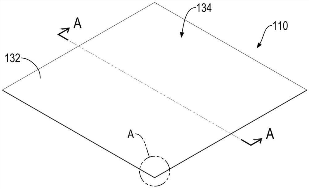
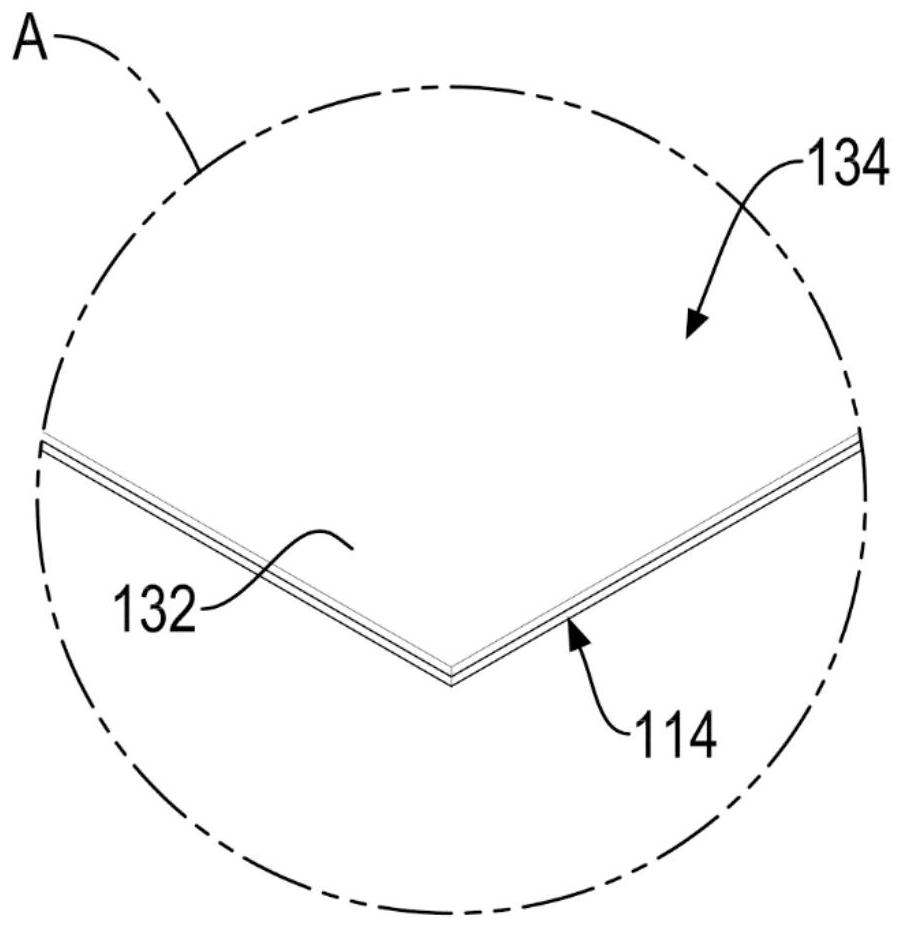
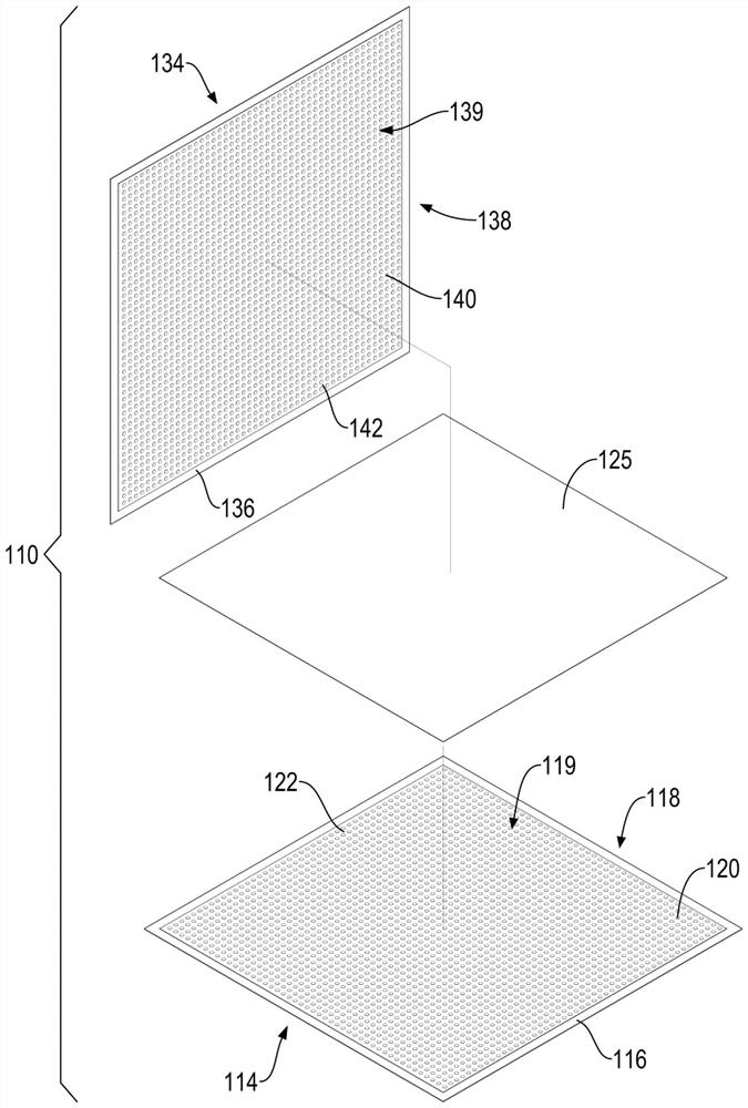
[0051] The present invention relates to a vapor chamber. Please refer to Fig. 1 to Fig. 3. It can be seen from the figures that the vapor chamber 110 of the present invention includes a top shell 134, a bottom shell 114 and a capillary structure 125. The top shell 134 and the bottom shell 114 have a first surface 132, 112 and a second surface 138, 118 respectively, wherein the first surface 132, 112 is used to thermally couple with the heat load of a heat source, such as the first surface 112 of the bottom shell 114 , and each second surface 138, 118 has a heat exchange area 139, 119 surrounded by an outer ring portion 136, 116, each heat exchange area 139, 119 includes a plurality of evaporation areas 142, 122 Separated surface features 140, 120, preferably, the top case 134 and the bottom case 114 are made of a heat-conducting material with relatively high heat-conducting efficiency, such as copper or aluminum, and the first surfaces 132, 112 thereof are a plane, It is used ...


PUM


Abstract

The present invention relates to a vapor chamber and manufacturing method for the same, the vapor chamber having upper and lower casings and a wick structure. The upper and lower casings have upper and lower heat exchange chamber areas having multiple upper and lower surface features thereon, separated by multiple upper and lower vapor areas therebetween, respectively. The upper and lower heat exchange chamber areas are surrounded by walls, having flat rims, respectively. The upper and lower heat exchange chamber areas form a vacuum chamber. An airtight sealed connection is formed at the flatrims of the surrounding walls of the upper and lower heat exchange chamber areas. Accordingly, a vapor chamber having an increasing condensing area and improved heat dissipating effect is provided toprevent deformation and leakage.

Description

technical field [0001] The invention relates to the technical field of heat conduction, in particular to a heat chamber for thermal management of a computer or an electronic device and a manufacturing method thereof. Background technique [0002] When a computer or electronic device is operating, it is necessary to quickly and efficiently discharge the heat generated by its internal central processing unit (CPU) or other processing units, so that its temperature can be kept within the design range. Today's central processing unit As components such as units are designed to be lighter, smaller and more powerful, more heat will be generated in a smaller space, making thermal management of electronic devices more challenging than ever. [0003] The thermal management technology of existing electronic devices mainly includes air-cooled and liquid-cooled. A vapor chamber in the form of a planar heat pipe can be used alone or connected with a heat conduction heat management system...

Claims


Application Information

Patent Timeline
Patent Type & Authority Applications(China)
IPC IPC(8): F28D15/04
CPCF28D15/04F28F3/12F28D15/0233F28D15/046F28F3/044F28F3/046F28F3/048F28F2230/00F28F2210/10
Inventor 郑任智
Owner COOLER MASTER CO LTD
Why Eureka
Try Eureka