Group hole measurement swing angle planning method based on three-coordinate probe

A three-coordinate and stylus technology, applied to measuring devices, instruments, etc., can solve problems such as reducing the efficiency of group holes, and achieve the effects of improving calibration efficiency and reducing swing angles

Active Publication Date: 2020-12-04
CHENGDU AIRCRAFT INDUSTRY GROUP
View PDF13 Cites 4 Cited by
  • Summary
  • Abstract
  • Description
  • Claims
  • Application Information

AI Technical Summary

Problems solved by technology

Due to the large number of guide holes on the part, they form a group of holes, and the axes of each hole are diffe

Method used


Image

  • Group hole measurement swing angle planning method based on three-coordinate probe
  • Group hole measurement swing angle planning method based on three-coordinate probe
  • Group hole measurement swing angle planning method based on three-coordinate probe

Examples


Embodiment 1

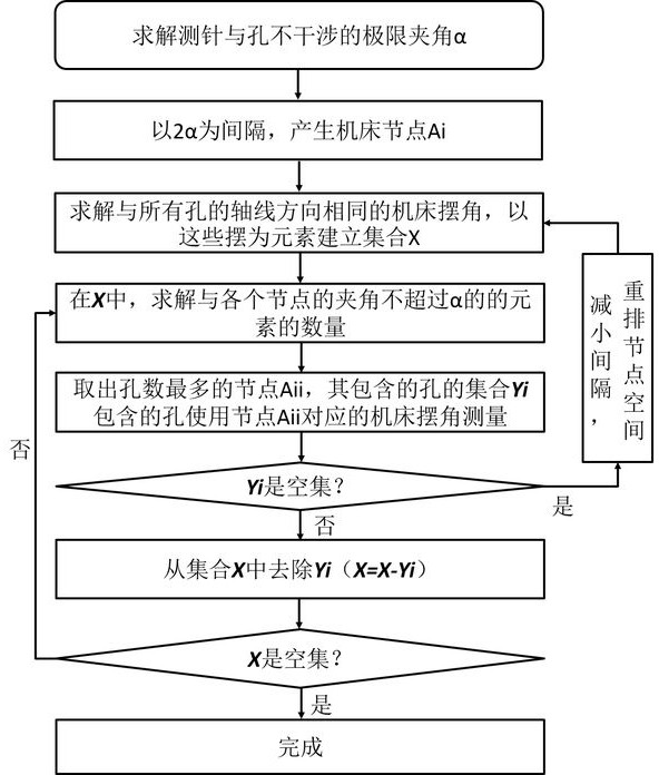
[0029] A three-coordinate stylus-based pendulum angle planning method for group hole measurement, characterized in that it includes:

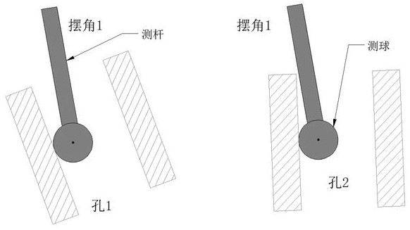
[0030] 1) According to the characteristic parameters of the stylus and the hole to be measured, solve the limit angle α at which the stylus does not interfere with the hole;

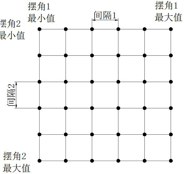
[0031] 2) Divide the range of the two swing angles of the measuring machine / machine tool evenly at an interval of 2α to generate the machine tool node Ai;

[0032] 3) Solve the pendulum angle of the machine tool in the same direction as the axis of all holes, and use these pendulums as elements to establish a set X ;

[0033] 4) at X In , find the number of elements whose angles with each node do not exceed α;

[0034] 5) Take out the node Aii with the largest number of elements, and the set of holes corresponding to the elements contained in it Yi That is, the set of holes measured using the swing angle of the machine tool corresponding to node Aii;

[0035] 6) if ...

Embodiment 2

[0038] figure 1 A flow chart of a planning method for group hole measurement swing angle based on a three-coordinate stylus provided in an embodiment of the present invention, specifically including the following steps:

[0039] 1) According to the characteristic parameters of the stylus and the hole to be measured, solve the limit angle α at which the stylus does not interfere with the hole;

[0040] 2) Divide the range of the two swing angles of the measuring machine / machine tool evenly at an interval of 2α to generate the machine tool node Ai;

[0041] 3) Solve the pendulum angle of the machine tool in the same direction as the axis of all holes, and use these pendulums as elements to establish a set X ;

[0042] 4) at X In , find the number of elements whose angles with each node do not exceed α;

[0043] 5) Take out the node Aii with the largest number of elements, and the set of holes corresponding to the elements contained in it Yi That is, the set of holes measur...


PUM


Abstract

The invention relates to the field of aircraft geometric quantity measurement, in particular to a group hole measurement swing angle planning method based on a three-coordinate probe. The method comprises the following steps: 1) solving a limit included angle alpha between the probe and a hole without interference; 2) generating a machine tool node Ai by taking 2alpha as an interval; 3) solving the relative swing angle of the machine tool, and establishing a set X; 4) solving the number of elements which do not exceed alpha from the X; 5) taking out the node Aii with the largest element number; (6) if Yi is a null set, reducing the interval, dividing again to generate more dense nodes, and repeating the step (3) and the step (5); and 7) after the Yi is removed, if X is a null set, completing planing and if X is not a null set, repeating the step 4) until X is a null set. According to information such as the size of the three-coordinate probe and measurement parameters of the group hole, group hole measurement under the machine tool swing angle can be realized as little as possible, the swing angle needing to be calibrated is reduced, and the calibration efficiency of the group holehigh-precision measurement based on the three-coordinate probe is improved.

Description

technical field [0001] The present application relates to the field of measurement of aircraft geometric quantities, in particular to a method for planning the swing angle of group hole measurement based on a three-coordinate stylus. Background technique [0002] In order to meet the connection strength requirements of aircraft, aircraft parts generally have a large number of guide holes for installing bolts or rivets. With the improvement of aircraft performance requirements, aircraft parts are more curved and complex, which makes the normal distribution of the guide holes on the parts different, and the accuracy requirements for the hole positions and apertures of the guide holes are also higher. [0003] At present, the measurement of the hole position and diameter of the hole is generally carried out by using a three-coordinate stylus on a three-coordinate measuring machine or a five-axis machine tool through a probe measurement method. In order to avoid the interferenc...

Claims


Application Information

Patent Timeline
IPC IPC(8): G01B21/14G01B21/00G01B21/22
CPCG01B21/14G01B21/00G01B21/22
Inventor 易晓满黄明聪沈昕唐李王鹏程李卫东
Owner CHENGDU AIRCRAFT INDUSTRY GROUP
Why Eureka
Try Eureka