New energy button battery pack

A battery pack and new energy technology, applied in battery pack components, batteries, secondary batteries, etc., can solve the problems of complex battery box structure, inconvenient battery pack maintenance, new energy battery replacement, and inconvenient disassembly, etc. The effect of high discharge rate, easy maintenance, easy replacement and maintenance

Inactive Publication Date: 2020-12-04
何秀丽
View PDF0 Cites 0 Cited by
  • Summary
  • Abstract
  • Description
  • Claims
  • Application Information

AI Technical Summary

Problems solved by technology

[0003] Most of the existing new energy battery packs are one-piece structures. The battery packs are fixed and installed according to certain placement rules through a specific installation structure, and split-type combination installation and disassembly cannot be performed.
At present, the new energy battery pack is generally installed in the battery box as a whole. Once the new energy battery pack fails, the battery box needs to be disassembled for maintenance of the new energy battery pack. The traditional battery box has a complex structure and is inconvenient to disassemble and repair. Personnel repair the battery pack and replace the new energy battery

Method used


Image

  • New energy button battery pack
  • New energy button battery pack
  • New energy button battery pack

Examples


Embodiment Construction

[0027] The following will clearly and completely describe the technical solutions in the embodiments of the present invention with reference to the accompanying drawings in the embodiments of the present invention. Obviously, the described embodiments are only some, not all, embodiments of the present invention. Based on the embodiments of the present invention, all other embodiments obtained by persons of ordinary skill in the art without creative efforts fall within the protection scope of the present invention.

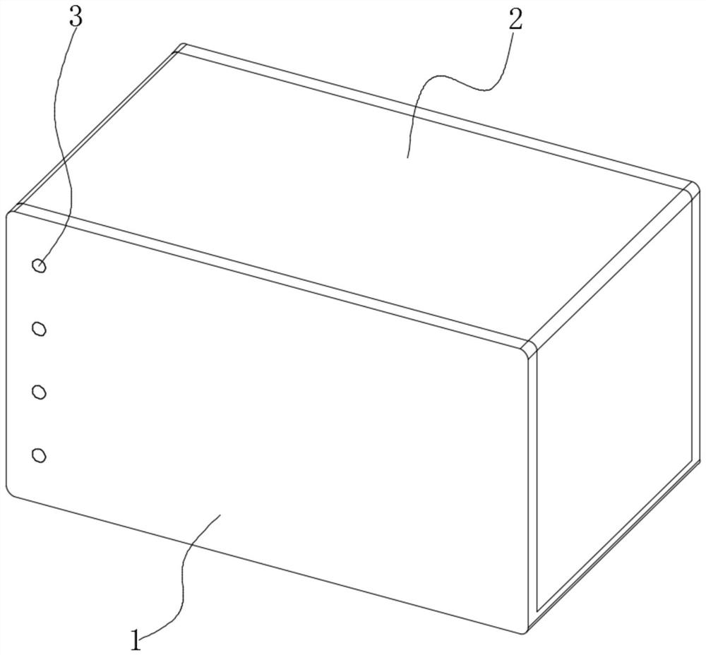
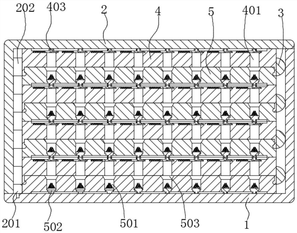
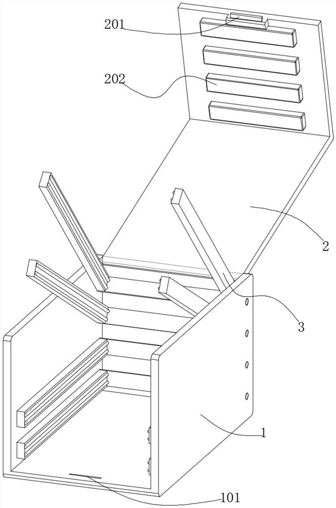
[0028] see Figure 1-8 As shown, the present invention is a new energy button battery pack, including a battery box 1, the top of the battery box 1 is hinged with a box cover 2, and the bottom end of the box cover 2 is engaged with the inner bottom of the battery box 1; the battery box There is a row of U-shaped frames 3 that are rotated in 1, and a battery board is clamped inside the U-shaped frame 3. The battery board includes an upper plate 4 and a lower plate 5...


PUM


Abstract

The invention discloses a new energy button battery pack, and relates to the technical field of new energy batteries. The new energy button battery pack comprises a battery box, wherein a box cover ishinged to the top part of the battery box, and the bottom end of the box cover is clamped and matched with the inner bottom part of the battery box; a row of U-shaped frames are rotatably matched inthe battery box, a battery panel is clamped in the U-shaped frames, and the battery panel comprises an upper plate and a lower plate which are clamped and matched with each other; round holes are formed in the bottom end surface of the upper plate at intervals, limiting sliding blocks corresponding to the round holes are arranged at the top end of the upper plate, and notches are formed in the bottom end faces of the limiting sliding blocks; and limiting holes corresponding to the round holes are formed in the upper surface of the lower plate, and the inner bottom parts of the limiting holes are in sliding fit with bottom supports. According to the new energy button battery pack, new energy batteries are fixedly installed according to a certain installation sequence through cooperation ofthe upper plate and the lower plate, the positions of the new energy batteries are limited through cooperation of the bottom supports and the limiting sliding blocks, and maintenance of the battery panels and replacement of the single new energy batteries are facilitated.

Description

technical field [0001] The new energy battery of the invention belongs to the technical field, and in particular relates to a new energy button battery pack. Background technique [0002] A large number of new energy batteries need to be installed on electric vehicles, and new energy batteries are installed in the form of battery packs; new energy battery packs refer to the series or parallel connection of new energy batteries, and the parallel new energy battery packs require each battery The voltage is the same, and the output voltage is equal to the voltage of a battery. Parallel battery packs can provide stronger current. New energy battery packs have the advantages of high energy density, high power, small self-discharge, and high charging efficiency. The scope of use of new energy battery packs Large, widely used in mobile devices, aerospace and new energy vehicles and other fields. [0003] Most of the existing new energy battery packs have an integrated structure. T...

Claims


Application Information

Patent Timeline
Patent Type & Authority Applications(China)
IPC IPC(8): H01M2/10H01M10/42B60L50/64
CPCB60L50/64H01M10/4207H01M2220/20Y02E60/10Y02T10/70
Inventor 何秀丽
Owner 何秀丽
Why Eureka
Try Eureka