Stamp hole module radio frequency test PAD layout structure and radio frequency test fixture thereof

A technology for radio frequency testing and layout structure, applied in transmission monitoring, digital transmission systems, data exchange networks, etc., can solve problems such as waste, affecting radio frequency performance, antenna tail difference, etc., and achieve improved radio frequency performance, good shielding ground contact, and good The effect of RF performance

Active Publication Date: 2020-12-04
美唐科技(江苏)有限公司
View PDF3 Cites 0 Cited by
  • Summary
  • Abstract
  • Description
  • Claims
  • Application Information

AI Technical Summary

Problems solved by technology

[0003] However, for the existing RF test pin structure, there are two common methods for the layout of the PAD at the bottom of the module: the first layout method discards the module PIN, and sets the center point of the PIN on the RF antenna pad of the module as the center, and sets around it. A circle of PAD pads is in contact with the shielding PAD of the outer ring of the test pin. The disadvantage is that the two module PINs around the center point of the RF antenna pad PIN of the module will be discarded, causing some waste; the second type of center test Point extension layout method, on the basis of method 1, the RF calibration antenna test point is moved up, and with this test point as the center, a circle of ground PAD pads is set around it, which is in contact with the outer ring shielding PAD of the test pin , although it will not occupy the space of the PIN pin, its disadvantage is that there will be a period of antenna tail difference in the formal application of the module, which will slightly affect the RF performance

Method used


Image

  • Stamp hole module radio frequency test PAD layout structure and radio frequency test fixture thereof
  • Stamp hole module radio frequency test PAD layout structure and radio frequency test fixture thereof
  • Stamp hole module radio frequency test PAD layout structure and radio frequency test fixture thereof

Examples


Embodiment Construction

[0030] The following will clearly and completely describe the technical solutions in the embodiments of the present invention with reference to the accompanying drawings in the embodiments of the present invention. Obviously, the described embodiments are only some, not all, embodiments of the present invention. Based on the embodiments of the present invention, all other embodiments obtained by persons of ordinary skill in the art without making creative efforts belong to the protection scope of the present invention.

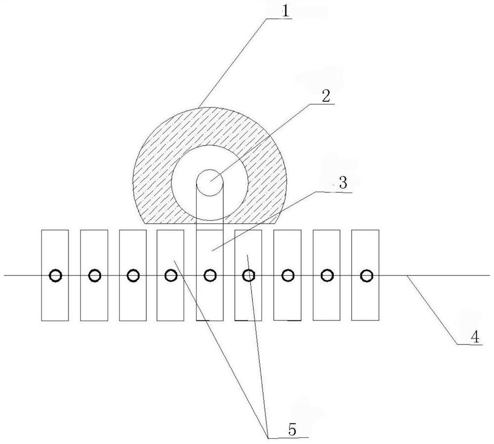
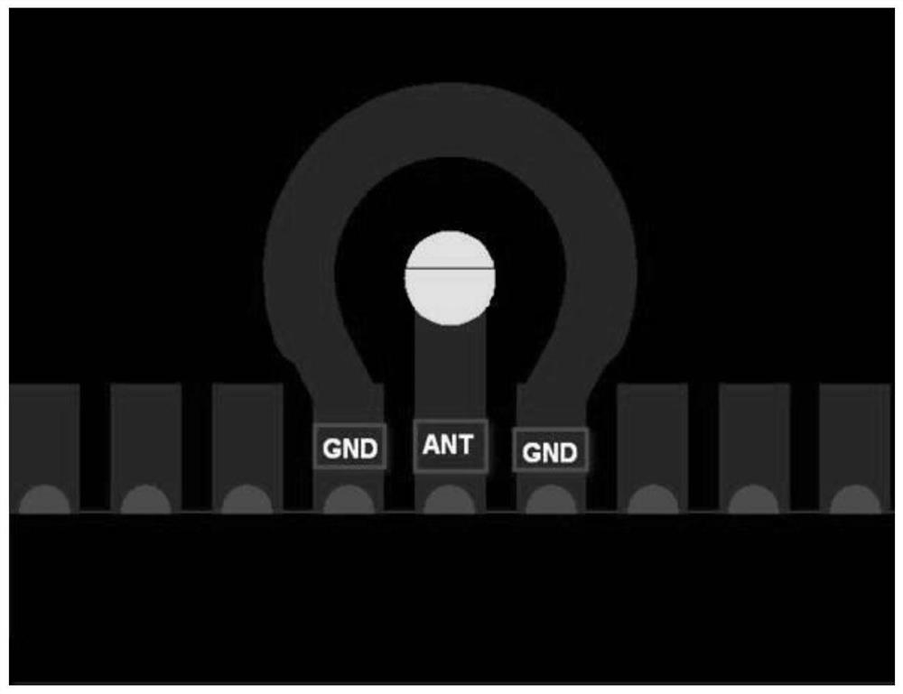
[0031] The embodiment of the invention discloses a stamp hole module radio frequency test PAD layout structure and a radio frequency test fixture thereof. see figure 1 The stamp hole module includes the RF antenna PIN3 of the antenna RF test point, the ground PAD pad 1, and the antenna RF test point 2 and the ground PAD pad 1 are located on the same plane. During the production of the stamp hole communication module, the radio frequency needs to be pre-calibr...


PUM


Abstract

The invention discloses a stamp hole module radio frequency test PAD layout structure and a radio frequency test clamp thereof. The plate edge of a stamp hole module is provided with a plate edge PIN,the stamp hole module comprises a radio frequency antenna PIN serving as an antenna radio frequency test point and a ground PAD bonding pad, the A end of the radio frequency antenna PIN is located onthe plate edge, and the B end of the radio frequency antenna PIN is located in the center of the ground PAD bonding pad; the ground PAD bonding pad is a cutting annular bonding pad; the cutting edgeof the cutting annular bonding pad faces the direction of the board edge where the board edge PIN is located; the radio frequency test fixture comprises a radio frequency test needle and a test needleplate sleeve; the radio frequency test pin comprises an outer ring shielding PAD which is used for being electrically connected with the ground PAD bonding pad and is matched with the ground PAD bonding pad in shape; and the test needle plate sleeve is used for fixing and limiting the radio frequency test needle. According to the invention, through the distance between the radio frequency test point PAD and the radio frequency antenna PAD, the length of a radio frequency wire is reduced, the radio frequency performance is improved, and the waste in production is avoided. Meanwhile, the radiofrequency test needle is correspondingly in contact with the ground PAD bonding pad after metal cutting to obtain the radio frequency test fixture.

Description

technical field [0001] The invention relates to the technical field of application terminals in the communication module industry, and more specifically relates to a stamp hole module radio frequency test PAD layout structure and a radio frequency test fixture thereof. Background technique [0002] At present, in the production of all stamp hole communication modules, the radio frequency needs to be pre-calibrated. Generally, the PAD at the bottom of the module has a radio frequency test point reserved, which is connected to the radio frequency test pin on the production fixture for calibration and comprehensive testing. The central test point of the RF test needle is connected to the RF antenna PIN on the module, and the metal shielding PAD around the RF test needle is connected to the ground PAD around the antenna PIN on the module to maintain good RF performance. [0003] However, for the existing RF test pin structure, there are two common methods for the layout of the P...

Claims


Application Information

Patent Timeline
Patent Type & Authority Applications(China)
IPC IPC(8): H04B17/00H04L12/26
CPCH04B17/00H04L43/50
Inventor 顾晗
Owner 美唐科技(江苏)有限公司
Why Eureka
Try Eureka