A concealed inverted tube sound bar structure
A technology of sound bar speakers and inverter tubes, which is applied to the space/structural arrangement of speakers, transducer shells/cabinets/brackets, etc., which can solve the problems of increased difficulty in assembly operations and inconvenient installation of inverter tubes
- Summary
- Abstract
- Description
- Claims
- Application Information
AI Technical Summary
Problems solved by technology
Method used
Image
Examples
Embodiment 1
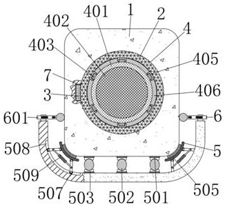
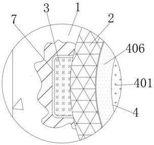
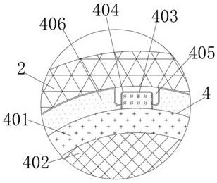
[0031] A concealed inverter tube sound bar structure, comprising a sound bar speaker 1, the middle installation end of the sound bar speaker 1 is provided with an inverter tube 2, and the outer walls of the left and right sides of the inverter tube 2 are fixedly connected with first sliders 3. The first slider 3 is slidingly connected with the first chute 7, and the first chute 7 is set on the middle inner wall of the left and right sides of the sound bar 1, and the inverter tube 2 is installed through the first slider 3 on both sides In the second chute 7 on both sides of the sound bar speaker 1, and the first slider 3 is made of hard rubber material to enhance the sealing performance, the middle front end of the inverter tube 2 is equipped with a dust-proof mechanism 4, the dust-proof mechanism 4 includes a circular plate 401, a filter screen 402, a second slider 403, a second chute 404, a block 405 and a rubber pad 406, a filter screen 402 is arranged in the middle of the ci...
Embodiment 2
[0033] As an option, see figure 1 , 4, 5 and 6, concealed inverter tube sound bar structure, a buffer mechanism 5 is installed under the sound bar 1, and the buffer mechanism 5 includes a first splint 501, a rubber ball 502, a second splint 503, a rubber block 504, a curved Rod 505, inclined rod 506, roller 507, third chute 508, first compression spring 509 and curved plate 510, the top of the first splint 501 fits with the bottom end of the left side of the sound bar 1, and the three first The splint 501 supports the sound bar speaker 1, the rubber ball 502 is arranged under the first splint 501, the lower middle inner wall of the first splint 501 is fixedly connected with the upper outer wall of the rubber ball 502, and the second splint is arranged under the rubber ball 502 503, the bottom end of the rubber ball 502 is fixedly connected to the upper middle inner wall of the second splint 503, and the elasticity of the three rubber balls 502 can offset the vibration force g...
Embodiment 3
[0036] As an option, see figure 1 with 4 , a concealed inverted tube sound box structure, a fixing mechanism 6 is installed on the left and right sides above the curved plate 510, and the fixing mechanism 6 includes a cross bar 601, a groove 602, a top block 603, a vertical plate 604, and a second compression spring 605, fixed ball 606 and handle 607, a groove 602 is provided in the middle of the left side of the cross bar 601, the left inner surface of the groove 602 fits with the front end outer wall of the top block 603, and the rear end of the top block 603 is fixedly connected to the The upper middle front end of the vertical plate 604, the groove 602 on the cross bar 601 moves outward on the outer wall of the top block 603 at the front end of the vertical plate 604, the bottom end of the vertical plate 604 is fixed on the left top of the curved plate 510, and the groove A second compression spring 605 is affixed to the inner surface of the right side of 602, and the lef...
PUM
 Abstract
Description
Claims
Application Information
 - R&D
- Intellectual Property
- Life Sciences
- Materials
- Tech Scout
- Unparalleled Data Quality
- Higher Quality Content
- 60% Fewer Hallucinations
Browse by: Latest US Patents, China's latest patents, Technical Efficacy Thesaurus, Application Domain, Technology Topic, Popular Technical Reports.
© 2025 PatSnap. All rights reserved.Legal|Privacy policy|Modern Slavery Act Transparency Statement|Sitemap|About US| Contact US: help@patsnap.com


