Visual dental descaler

A tooth scaler and host technology, applied in the field of oral cleaning appliances, can solve problems such as easy blocking of light sources and difficulties in doctor's observation, and achieve the effect of solving dental calculus

Pending Publication Date: 2020-12-08
GUANGZHOU T K MEDICAL INSTR
View PDF0 Cites 5 Cited by
  • Summary
  • Abstract
  • Description
  • Claims
  • Application Information

AI Technical Summary

Problems solved by technology

[0005] During the cleaning process, doctors usually rely on external light sources to illuminate the oral cavity, but during the operation, because the doctor needs to lower his head to observe the inside of the oral cavity, it is very easy to block the light source illumination
In particular, when cleaning the outside of the molars in the deep oral cavity, coupled with the fact that the working site is located in the deep oral cavity and covered by the cheek muscles, it is very difficult for the doctor to observe during the operation, and it is often necessary to adjust the head posture or bend the waist to adapt to the teeth cleaning. Visual field observation, and the long-term working state of the doctor with his head down is very easy to cause cervical spondylosis, lumbar spine and other diseases

Method used


Image

  • Visual dental descaler
  • Visual dental descaler
  • Visual dental descaler

Examples


Embodiment 1

[0076] Embodiment 1: The visible tooth scaler of the present invention

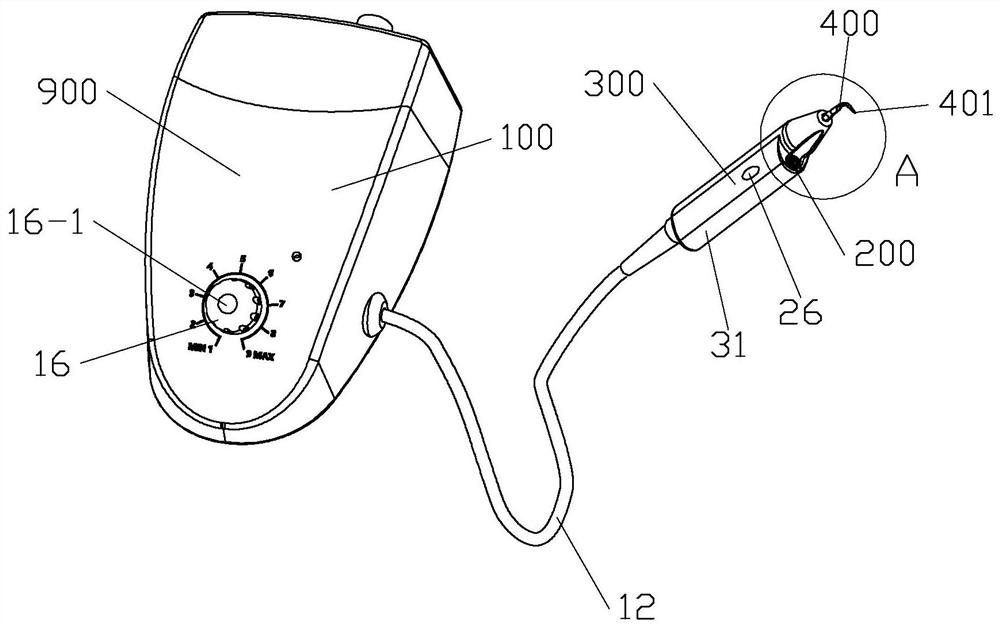
[0077] refer to Figure 1 to Figure 1-3 , the visual dental scaler of the present invention includes a main machine 100, an observation system 200, a handle 300 and a working part 400.

[0078] The host 100 includes a power supply system 11 , a circuit system 12 , a control system 13 , a motion generating system 14 and a casing 15 . The control system 13 is provided with a power switch 13-1 and a vibration drive switch 13-2. The power switch 13-1 is located on the housing 15, and the vibration-driven switch 13-2 is a foot switch 13-21, which is connected to the host 100 through the interface 15-1. Refer to image 3 .

[0079] In this embodiment, in order to ensure the safety of the working process, the control system 13 sets up the power supply and the control switch of the working state separately. In practical applications, the control switch of the power supply and the working state can also be comb...

Embodiment 2

[0096] Embodiment 2: The visual dental scaler of the present invention with adjustable lens

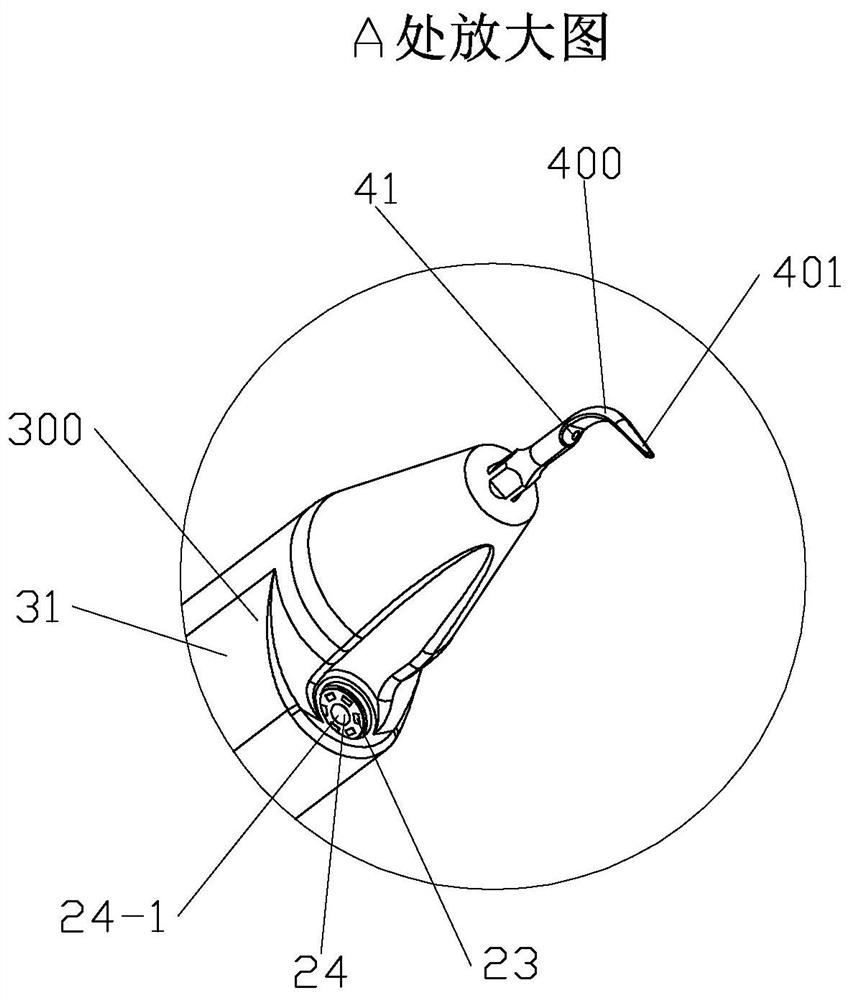
[0097] refer to Figure 5 to Figure 7-2 The difference between this embodiment and Embodiment 1 is that in this embodiment, the lens 24-1 of the camera system 24 protrudes from the housing 31 through the connecting mechanism 25, and by adjusting the shape of the connecting mechanism 25 and position, the position and angle of the lens 24-1 can be adjusted.

[0098] refer to Figure 5 to Figure 5-2 , the connecting structure 25 can be designed as a deformable serpentine tube structure, and in clinical use, the observation angle of the camera 24-1 can be adjusted by adjusting the serpentine tube.

[0099] refer to Figure 6 to Figure 6-2 , the connecting structure 25 can be folded or unfolded outside the handle 300 . The connecting mechanism 25 can be folded or unfolded around the rotating shaft 25-1, and the real-time folding or unfolding of the connecting mechanism 25 can drive the...

Embodiment 3

[0105] Embodiment 3: The visible tooth scaler of the present invention with detachable lens

[0106] refer to Figure 8 and Figure 9 The difference between this embodiment and Embodiment 2 is that in this embodiment, the observation system 200 is detachably installed on the handle 300 .


PUM


Abstract

A visual dental descaler in the invention comprises a main machine, an observation system, a handle and a working part; the observation system comprises a lighting system and a camera system; images shot by a camera of the camera system can be transmitted to a display in time; therefore, the process of cleaning dental calculus, dental plaque and pigmentation on the surfaces of teeth by the workingpart and the cleaning effect are observed immediately while cleaning is carried out; and the purposes of effectively cleaning, grinding and polishing the teeth are achieved. Due to the design of theobservation system, real-time observation in the cleaning process is guaranteed; clinical operation is relatively safe; meanwhile, a doctor can see the display for cleaning; and the working process isrelatively easy.

Description

technical field [0001] The invention relates to an appliance for cleaning the oral cavity, in particular to a visible tooth scaler for cleaning teeth and between teeth. Background technique [0002] When the teeth are not cleaned for a long time, or when smoking, drinking tea, or drinking alcohol for a long time, it is very easy to produce dental problems such as calculus, dental plaque, and pigmentation on the surface of the teeth. The routine way of removing dental problems such as dental calculus, dental plaque, pigmentation at present is to wash teeth in a professional stomatological hospital. [0003] At present, the commonly used method of removing dental calculus, dental plaque, and pigment deposition in the process of cleaning teeth is to use the high-speed rotating or vibrating working head of the dental cleaner, such as an ultrasonic dental cleaner, etc., to extend into the oral cavity, and the friction or vibration of the working head Under the action, the plaque...

Claims


Application Information

Patent Timeline
Patent Type & Authority Applications(China)
IPC IPC(8): A61C17/16A61C17/02A61C1/08A61B1/253A61B1/247A61B1/06A61B1/05
CPCA61C17/16A61B1/247A61B1/05A61B1/0638A61B1/253A61C17/0208A61C1/088A61C17/02A61B1/06A61C1/08
Inventor 周星苏文宇徐华苹罗丽飞王玉娥
Owner GUANGZHOU T K MEDICAL INSTR
Why Eureka
Try Eureka