Inner side pedal of numerical control milling machine

A CNC milling machine and foot pedal technology, which is applied in the direction of large fixed members, metal processing machinery parts, metal processing equipment, etc., can solve the problems such as easy slipping of the foot pedal, and achieve the purpose of increasing friction and increasing the degree of lubrication Effect

Active Publication Date: 2020-12-08
郑玲佳
View PDF11 Cites 1 Cited by
  • Summary
  • Abstract
  • Description
  • Claims
  • Application Information

AI Technical Summary

Problems solved by technology

[0003] Based on the inventor's discovery above, the inner side pedals of an existing CNC milling machine mainly have the following deficiencies, such as: the machine tool needs to be sprayed with coolant, and the coolant falls in the bottom groove and mixes with oil. When pouring a high-speed rotating workpiece, the workpiece will throw the coolant onto the pedals through the rotation, so that the coolant with oil will be attached to the pedals, causing the staff to stick to the pedals and easily slip

Method used


Image

  • Inner side pedal of numerical control milling machine
  • Inner side pedal of numerical control milling machine
  • Inner side pedal of numerical control milling machine

Examples


Embodiment 1

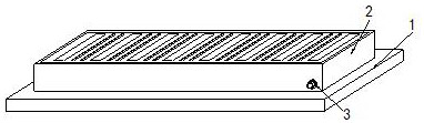
[0026] Example 1: Please refer to Figure 1-Figure 5 , the specific embodiments of the present invention are as follows:

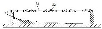
[0027] Its structure includes a base 1, a pedal 2, and a sewage outlet 3. The upper end of the base 1 is provided with a pedal 2, and the sewage outlet 3 is located at the bottom of the front end of the pedal 2. The pedal 2 includes a storage Water tank 21, liquid guiding device 22, water inlet 23, described water accumulation tank 21 is arranged on the inside of pedal 2, and height gradually decreases from one end to the other end, and described liquid guiding device 22 is provided with more than four cores, and horizontal Arranged on the top of the pedal 2, there are more than four water inlets 23, which are respectively located at the two ends of the liquid guiding device 22.

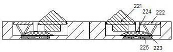
[0028] The liquid guiding device 22 includes a water guiding block 221, a trigger block 222, a sliding groove 223, a sliding block 224, and a return spring 225. There are two wa...

Embodiment 2

[0032] Example 2: Please refer to Figure 6-Figure 8 , the specific embodiments of the present invention are as follows:

[0033] The trigger block 222 includes a supporting link b1, a mounting seat b2, and a contact layer b3. The supporting link b1 is V-shaped, and the mounting seat b2 is embedded on the top of the supporting link b1. The contact layer b3 Attached to the top of the mounting seat b2, the contact layer b3 is made of rubber, and the top end surface is zigzag, which is beneficial to increase the friction between the trigger block 222 and the sole.

[0034] The supporting link b1 includes a connecting seat b11, a sliding friction block b12, a ball b13, and a friction device b14. The connecting seat b11 is embedded at both ends of the top of the supporting link b1, and the sliding friction block b12 is arranged At the bottom of the rod b1, there are more than three balls b13 arranged horizontally at the bottom of the sliding friction block b12. The friction device...


PUM


Abstract

The invention discloses an inner side pedal of a numerical control milling machine. The inner side pedal structurally comprises a base, a pedal body and a drain outlet, the pedal body is arranged at the upper end of the base, and the drain outlet is located in the bottom of the front end of the pedal body; the pedal body comprises a water accumulation groove, a liquid guide device and a water inlet, wherein the liquid guide device comprises a water guide block, a trigger block, a sliding groove, a sliding block and a reset spring; and the water guide block comprises a supporting seat, a friction block, a foot stepping block, a rotating block and an elastic rod, wherein the rotating block comprises a clamping groove, a supporting head, a rubber layer and a sunken groove. According to the inner side pedal, when a worker stands at the upper end of the pedal body 2, the water guide block extrudes the sliding block, so that the sliding block drives the trigger block to ascend to make contact with the shoe sole of a worker, friction force between the shoe sole and the pedal body is increased, and the situation that a worker slips on the pedal body is avoided.

Description

technical field [0001] The invention relates to the field of numerical control equipment, in particular to an inner pedal of a numerical control milling machine. Background technique [0002] The inner foot pedal of the CNC milling machine is installed on the outside of the CNC machine tool for the staff to stand on. The height of the foot pedal is higher than the ground, which allows the staff to stand higher and makes it easier for the staff to check the machine tool. It can make the staff operate the machine tool more smoothly, and avoid the situation that the machine tool needs to be raised for a long time to cause hand fatigue. [0003] Based on the inventor's discovery above, the inner side pedals of an existing CNC milling machine mainly have the following deficiencies, such as: the machine tool needs to be sprayed with coolant, and the coolant falls in the bottom groove and mixes with oil. When pouring a high-speed rotating workpiece, the workpiece will throw the co...

Claims


Application Information

Patent Timeline
IPC IPC(8): B23Q1/72B25H5/00
CPCB23Q1/72B25H5/00
Inventor 杨玉华
Owner 郑玲佳
Why Eureka
Try Eureka