Flat suction machining method for circular PIN part

A processing method, circular technology, applied in the direction of metal processing equipment, manufacturing tools, grinding workpiece supports, etc., can solve the problems of round PIN needles that are easy to jump, waste auxiliary time, and poor size control, so as to save The effect of leveling the parts, ensuring the machining accuracy and shortening the machining cycle

Active Publication Date: 2020-12-08
宝利根(成都)精密工业有限公司
View PDF10 Cites 0 Cited by
  • Summary
  • Abstract
  • Description
  • Claims
  • Application Information

AI Technical Summary

Problems solved by technology

[0003] ①The clamping time is too long, and it needs to be leveled with a calibration table, which wastes auxiliary time
②The concentricity of the front and rear ends of the processed circle will deviate, and the circle is prone to conical circles
③ The amount of cutting knife is not uniform, there will be uneven heating, and the size is not easy to control
④The contact point is too small, and the machine tool is running at high speed, causing the circular PIN needle to jump easily when rotating (commonly known as: spring knife), and a flat section will appear on the circular PIN needle, which is scrapped
[0004] To sum up, the processing time of parts is too long, and the quality is not easy to control, resulting in high cost of parts processing

Method used


Image

  • Flat suction machining method for circular PIN part
  • Flat suction machining method for circular PIN part

Examples


Embodiment Construction

[0025] The specific embodiments of the present invention are described below so that those skilled in the art can understand the present invention, but it should be clear that the present invention is not limited to the scope of the specific embodiments. For those of ordinary skill in the art, as long as various changes Within the spirit and scope of the present invention defined and determined by the appended claims, these changes are obvious, and all inventions and creations using the concept of the present invention are included in the protection list.

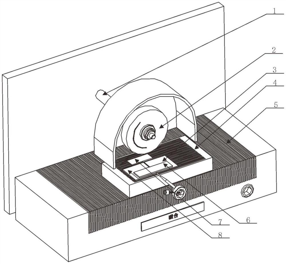
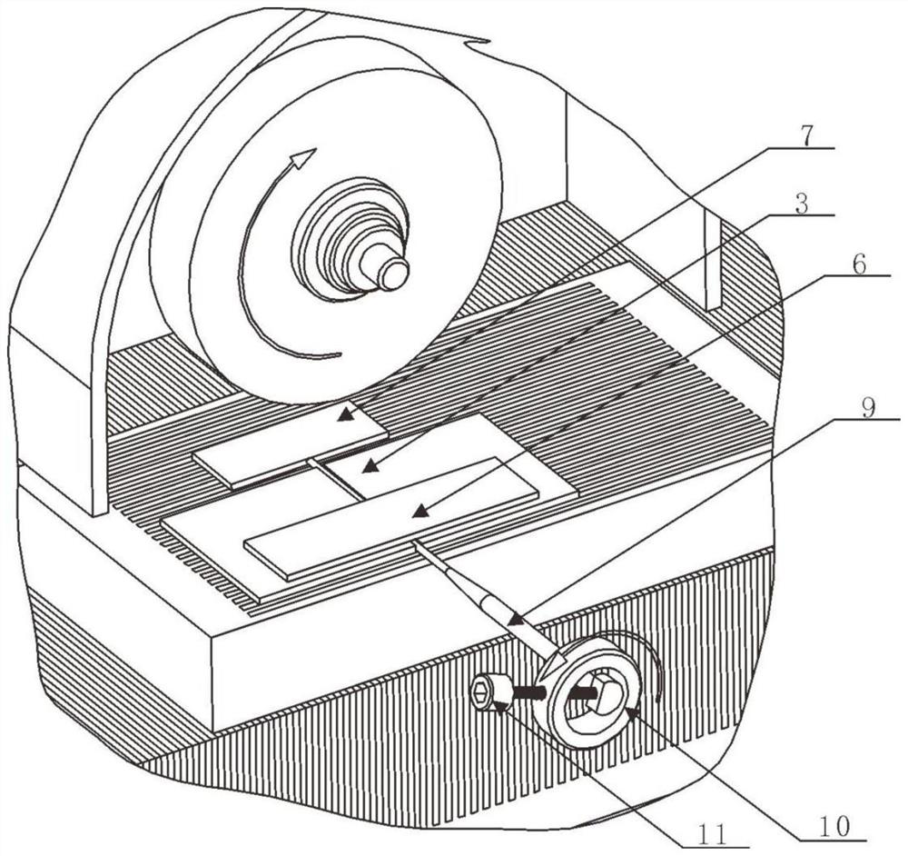
[0026] Combine below figure 1 and figure 2 The method for flat-suction processing of the circular PIN needle part 9 is described in detail, and the method S includes steps S1 to S2.

[0027] In step S1, select the suction force magnetic table 4 that width is less than the length of circular PIN needle part 9 to be placed on the magnetic table 5 of lathe, and make the magnetic line of force of suction force magnetic table ...


PUM


Abstract

The invention discloses a flat suction machining method for a circular PIN part. The flat suction machining method comprises the steps of selecting a suction magnetic table and placing the suction magnetic table on a magnetic table of a machine tool; fixing an ejector block and a first stop block on a suction magnetic table according to the machining length of the to-be-machined end of the circular PIN part; placing the to-be-machined end of the circular PIN part on the suction magnetic table, and making the top surface of the circular PIN part in contact with the block; placing a second stopblock on the opposite side of the first stop block, and making the first stop block and the second stop block clamp the length direction of the circular PIN part; placing a metal press block for pressing the circular PIN part on the first stop block and the second stop block; assembling a handle for rotating the circular PIN part at the unmachined end part of the circular PIN part, and then trimming a grinding wheel; and switching on the suction magnetic table, the magnetic table of the machine tool and a main shaft of the machine tool, and then rotating the circular PIN part to make contact with and be ground by the moving grinding wheel by using the handle until the to-be-machined end meets the design requirement of a drawing.

Description

technical field [0001] The invention relates to the processing technology of circular PIN needle parts, in particular to a flat suction processing method of circular PIN needle parts. Background technique [0002] In the processing of mold parts, round PIN needles are often processed, and round PIN needles are usually processed by punch formers (commonly known as: twisted circles). The chuck of the punch former clamps one end of the round PIN needle, and the other end is suspended Make the grinding wheel of the grinder touch the suspended part to achieve the shaping effect. However, after the circular PIN needle is suspended in the above processing method, there will be the following defects during processing: [0003] ①The clamping time is too long, and it needs to be leveled with a calibration table, which wastes auxiliary time. ②The concentricity of the front and rear ends of the processed circle will deviate, and the circle is prone to conical circles. ③ If the amount...

Claims


Application Information

Patent Timeline
Patent Type & Authority Applications(China)
IPC IPC(8): B24B5/36B24B41/06B24B27/02
CPCB24B5/36B24B41/06B24B27/02Y02P70/10
Inventor 廖培根陈安林朱天财谢彪郭维杨兵席刚郭芝忠林岗
Owner 宝利根(成都)精密工业有限公司
Why Eureka
Try Eureka