
Positioning device for machining outer circle gear teeth of automobile differential gear

An automotive differential and positioning device technology, applied in workpiece clamping devices, manufacturing tools, etc., can solve the problems of high scrap rate, small application range, single positioning diameter, etc., and achieve diversified positioning diameters and good clamping effect. , the effect of reducing the scrap rate

Inactive Publication Date: 2020-12-08
YANCHENG GAOYUE MACHINERY
View PDF0 Cites 0 Cited by
  • Summary
  • Abstract
  • Description
  • Claims
  • Application Information

AI Technical Summary

Problems solved by technology

In the production process of automobile differential gears, it is necessary to carry out various processing on the outer circular gear teeth. The gear positioning device currently used mainly has the following problems: 1. It can only position the gear shaft hole with a single diameter, and the positioning diameter is single. , the scope of application is small; 2. The shaft hole of the gear is easy to be clamped by the clamping part, resulting in the scrapping of the gear, the positioning effect is not ideal, and the scrapping rate is high; 3. After the gear is positioned, there are burrs on the edge of the shaft hole, which easily leads to uneven positioning; 4. , The existing gear positioning device cannot realize gear rotation processing after positioning

Method used


Image

  • Positioning device for machining outer circle gear teeth of automobile differential gear
  • Positioning device for machining outer circle gear teeth of automobile differential gear
  • Positioning device for machining outer circle gear teeth of automobile differential gear

Examples


Embodiment Construction

[0015] The specific content of the present invention will be described in detail below in conjunction with the accompanying drawings and specific embodiments.

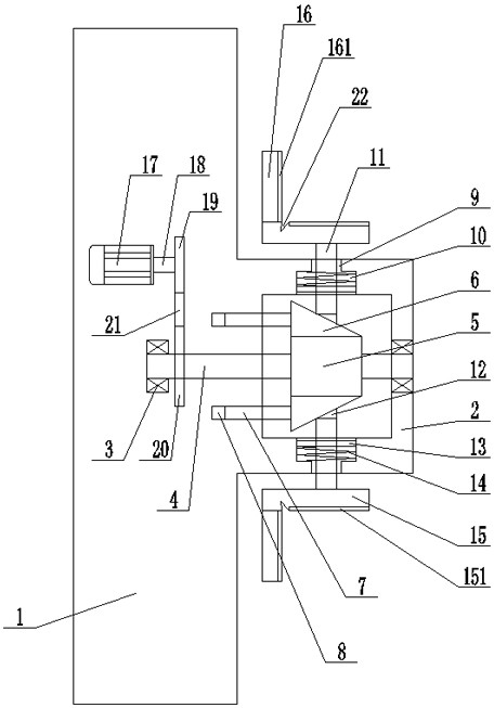
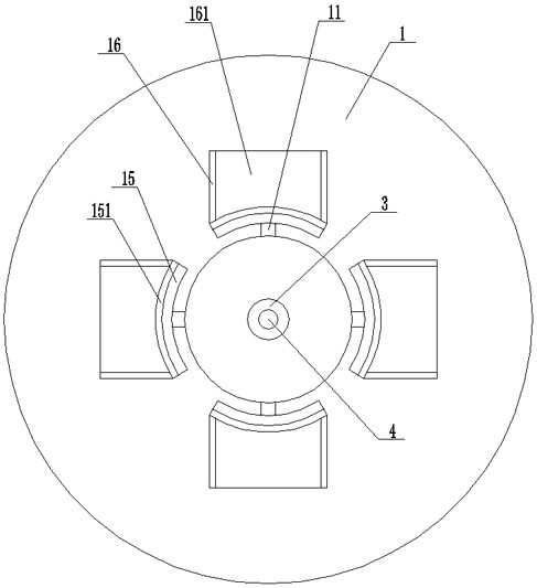
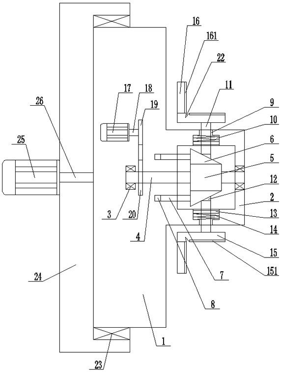
[0016] Such as figure 1 , figure 2 , image 3 As shown, the positioning device for the processing of the outer circular gear of the automobile differential gear includes: a fixed plate 1, an annular fixed sleeve 2 is arranged in the middle of the right side of the fixed plate 1, and an annular fixed sleeve 2 is arranged between the fixed plate 1 and the annular fixed sleeve. The middle part of 2 is provided with a transverse screw 4 through the rotation of the first bearing seat 3, and a transverse screw sleeve 5 cooperating with the transverse screw 4 is arranged in the annular fixed sleeve 2, and several horizontal screw sleeves 5 are uniformly arranged on the The first oblique wedge 6 is provided with transverse guide rods 7 respectively at the left end of the first oblique wedge 6, and a number of horizontal gui...


PUM


Abstract

The invention discloses a positioning device for machining outer circle gear teeth of an automobile differential gear. The positioning device comprises a fixing disc, an annular fixing sleeve is arranged in the middle of the right side of the fixing disc, and a transverse screw rod is rotatably arranged in the middles of the fixing disc and the annular fixing sleeve through first bearing seats; atransverse threaded sleeve cooperating with the transverse screw rod is arranged in the annular fixing sleeve, a plurality of first inclined wedges are evenly arranged on the transverse threaded sleeve, and transverse guide rods are arranged at the left ends of the first inclined wedges correspondingly; a plurality of transverse guide holes cooperating with the transverse guide rods are evenly formed in the portions, at the left ends of the first inclined wedges, of the fixing disc, and a plurality of sliding rod sliding holes corresponding to the first inclined wedges one to one are evenly formed in the annular fixing sleeve in the radial direction; and limiting block sliding holes communicating with the sliding rod sliding holes are formed in the portions, on the inner sides of the sliding rod sliding holes, of the annular fixing sleeve.

Description

technical field [0001] The invention relates to a processing equipment for auto parts, in particular to a positioning device for processing outer circular gear teeth of an automobile differential gear. Background technique [0002] The automobile differential is one of the more important accessories in the automobile transmission equipment, and the gear is an important part of the automobile differential. In the production process of automobile differential gears, it is necessary to carry out various processing on the outer circular gear teeth. The gear positioning device currently used mainly has the following problems: 1. It can only position the gear shaft hole with a single diameter, and the positioning diameter is single. , the scope of application is small; 2. The shaft hole of the gear is easy to be clamped by the clamping part, resulting in the scrapping of the gear, the positioning effect is not ideal, and the scrapping rate is high; 3. After the gear is positioned,...

Claims


Application Information

Patent Timeline
Patent Type & Authority Applications(China)
IPC IPC(8): B25B11/00
CPCB25B11/00
Inventor 徐加高徐跃杜琴
Owner YANCHENG GAOYUE MACHINERY
Learn More