Building module processing system

A module processing and construction technology, applied in the field of building material manufacturing, can solve the problems of inability to maintain product quality, inability to clean the mold, reduce work efficiency, etc., and achieve the effects of simple structure, convenient operation, and improved work efficiency

Inactive Publication Date: 2020-12-08
于志勇
View PDF7 Cites 3 Cited by
  • Summary
  • Abstract
  • Description
  • Claims
  • Application Information

AI Technical Summary

Problems solved by technology

[0002] For example, a concrete brick processing machine is disclosed in the publication number CN107932690A, which includes a body, an upper mold, a lower mold, and a hopper. The left side of the lower part of the body is equipped with a rotating driving wheel, and the right part of the body is equipped with a rotating passive wheel corresponding to the level of the rotating driving wheel. , the rotation driving wheel and the rotation driven wheel are connected by two front and rear chains, and there are several rotation pallets installed between the two chains, and the rotation driving motor is installed on the lower side of the rotation driving wheel, between the rotation driving motor and the rotation driving wheel Connected by a belt, a hopper is installed on the upper side of the right half of the body, a distribution box is installed at the bottom of the hopper, a distribution oil cylinder is installed on the right side of the distribution box, a distribution track is installed on the lower side of the distribution box, and a distribution bottom plate is installed on the bottom side of the distribution track. The upper part of the right part is equipped with an upper mold, the upper side of the upper mold is connected with the sliding sleeve of the upper mold, and the upper mold oil cylinder is installed on the upper side of the sliding sleeve of the upper mold, and the lower mold is installed on the lower side of the right part of the fabric bottom plate, and the lower side of the lower mold is connected with the lower mold Sliding sleeve, the lower die cylinder is installed on the lower side of the sliding sleeve of the lower mold, and the sliding sleeve of the upper mold and the sliding sleeve of the lower mold are installed on two vertical guide shafts; Cleaning, in the long-term working process, the quality of the product cannot be maintained, and manual cleaning is required during the cleaning process, which reduces work efficiency

Method used


Image

  • Building module processing system
  • Building module processing system
  • Building module processing system

Examples


specific Embodiment approach 1

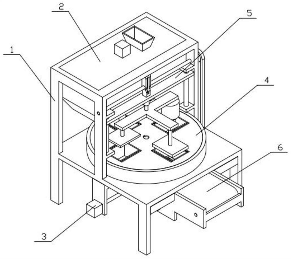
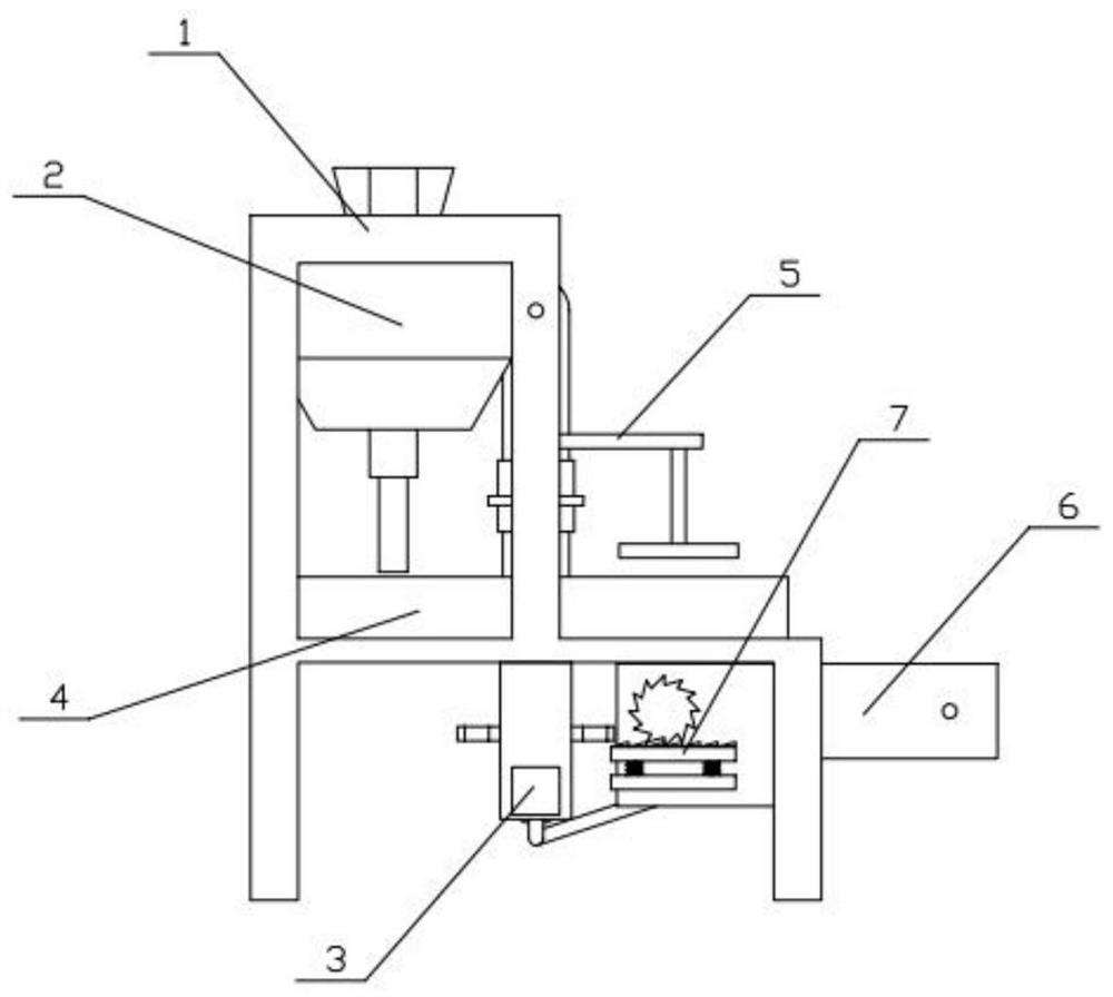
[0034] Combine below Figure 1-10 Describe this embodiment, a building module processing system, including a frame 1, a feeding mechanism 2, a power mechanism 3, a rotating mechanism 4, an extrusion mechanism 5, a conveying mechanism 6 and a transmission mechanism 7, the upper end of the frame 1 The feeding mechanism 2 is fixedly connected, the power mechanism 3 is fixedly connected to the lower end of the frame 1, the extruding mechanism 5 is connected to the frame 1, the extruding mechanism 5 is connected to the power mechanism 3, and the conveying mechanism 6 is fixedly connected to the On the frame 1, the transmission mechanism 7 is connected to the conveying mechanism 6, and the transmission mechanism 7 is connected with the power mechanism 3; The mutual cooperation of the extruding mechanism 5 and the intermittent movement of the rotating mechanism 4 and the conveying mechanism 6 are realized to complete extrusion, demoulding, cleaning and conveying, which improves the w...

specific Embodiment approach 2

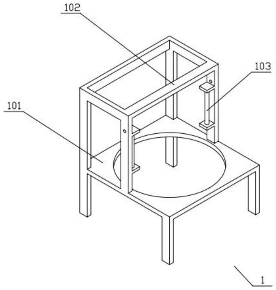
[0036] Combine below Figure 1-10 Describe this embodiment, this embodiment will further explain the first embodiment, the frame 1 includes a base 101, a bracket I 102 and a guide frame 103, the upper part of the base 101 is fixedly connected with the bracket I 102, and both sides of the bracket I 102 are fixedly connected with guide Frame 103 ; the setting of the guide frame 103 can ensure that the extruding mechanism 5 moves along the direction of the guide frame 103 .

specific Embodiment approach 3

[0038] Combine below Figure 1-10 Describe this embodiment, this embodiment will further explain the second embodiment, the feeding mechanism 2 includes a box body I201, a motor I202, a stirring frame 203 and a solenoid valve 204, the box body I201 is fixedly connected to the bracket I102, and the motor I202 Fixedly connected to the upper end of the box I201, the output shaft of the motor I202 is fixedly connected to the stirring frame 203, and the lower part of the box body I201 is fixedly connected to the solenoid valve 204; the stirring frame 203 is driven by the driving motor I202 to rotate, and the stirring frame 203 can Stir the material to prevent the material from agglomerating in the box I201, and prevent the material from clogging the lower part of the box I201. Institution 4.


PUM


Abstract

The invention relates to the field of building material manufacturing, and particularly relates to a building module processing system. The building module processing system comprises a rack, a feeding mechanism, a power mechanism, a rotating mechanism, an extruding mechanism, a conveying mechanism and a transmission mechanism, wherein the feeding mechanism is fixedly connected to the upper end ofthe rack; the power mechanism is fixedly connected to the lower end of the rack; the extruding mechanism is connected to the rack; the extruding mechanism is in transmission connection with the powermechanism; the conveying mechanism is fixedly connected to the rack; the transmission mechanism is connected to the conveying mechanism; and the transmission mechanism is connected with the power mechanism. According to the building module processing system, the power mechanism, the rotating mechanism, the extruding mechanism, the conveying mechanism and the transmission mechanism are matched with one another, so that the reciprocating motion of the extruding mechanism and the intermittent motion of the rotating mechanism and the conveying mechanism are realized, extruding, demolding, cleaning and conveying are completed, the working efficiency is improved, and meanwhile, the quality of products is guaranteed; and the device has the characteristics of being simple in structure and convenient to operate, and is worthy of popularization and use.

Description

technical field [0001] The invention relates to the field of building material manufacturing, in particular to a building module processing system. Background technique [0002] For example, a concrete brick processing machine is disclosed in the publication number CN107932690A, which includes a body, an upper mold, a lower mold, and a hopper. The left side of the lower part of the body is equipped with a rotating driving wheel, and the right part of the body is equipped with a rotating passive wheel corresponding to the level of the rotating driving wheel. , the rotation driving wheel and the rotation driven wheel are connected by two front and rear chains, and there are several rotation pallets installed between the two chains, and the rotation driving motor is installed on the lower side of the rotation driving wheel, between the rotation driving motor and the rotation driving wheel Connected by a belt, a hopper is installed on the upper side of the right half of the body...

Claims


Application Information

Patent Timeline
Patent Type & Authority Applications(China)
IPC IPC(8): B28B5/06B28B13/06B28B7/38B28B13/04B28B7/42B28B11/24
CPCB28B5/06B28B7/386B28B7/42B28B11/243B28B13/04B28B13/06
Inventor 于志勇
Owner 于志勇
Why Eureka
Try Eureka