Novel ultrasonic sensor
A sensor and ultrasonic technology, used in vehicle safety arrangements, bumpers, signal devices, etc., can solve the problems of narrow bumper thickness, difficult assembly, high product and mold cost, and achieve a wide range of thickness, high installation efficiency, and effective fixed effect
- Summary
- Abstract
- Description
- Claims
- Application Information
AI Technical Summary
Problems solved by technology
Method used
Image
Examples
Embodiment 1
[0028] The preferred embodiments of the present invention will be further described below in conjunction with the accompanying drawings.
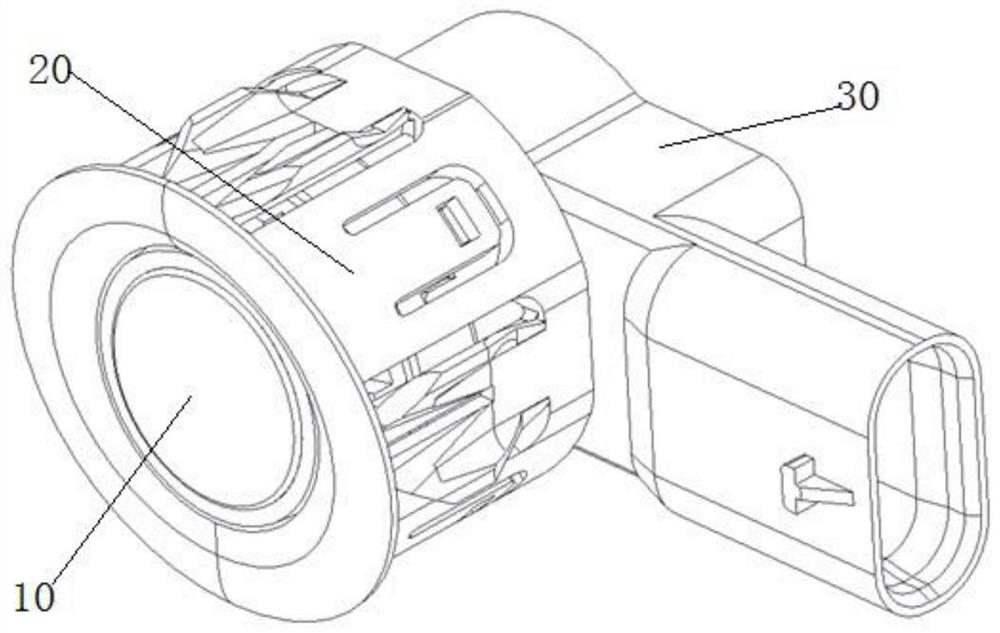
[0029] Such as figure 1 As shown, a novel ultrasonic sensor of the present invention is mainly composed of an ultrasonic probe 10 , a bracket 20 and a sensor 40 . The bracket 20 is sleeved on the periphery of the sensor 40, and the bracket 20 is an integrally formed plastic bracket.
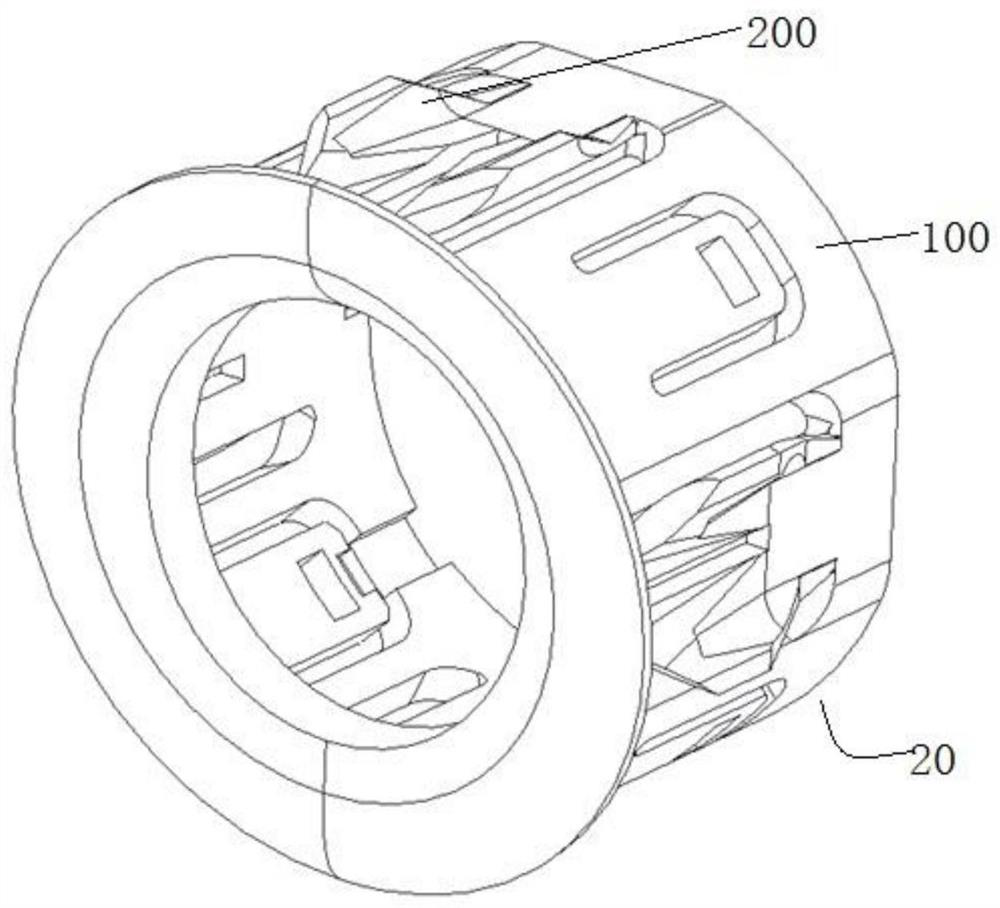
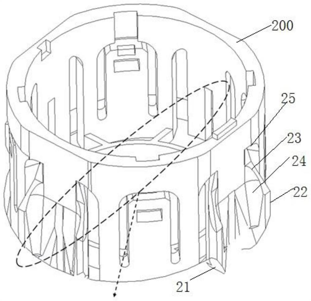
[0030] Such as figure 2 , 5 As shown, the bracket 20 includes a structural main body 100 and a clamping structure 200 arranged on the periphery of the structural main body 100. The structural main body 100 is used to fit on the periphery of the sensor, and the clamping structure 200 is clamped with the mounting hole. The sensor is generally installed on the bumper of a car. , the mounting holes are provided on the bumper. The clamping structure 200 includes a clamping body 25, radially arranged airfoil structures (22, 24) and axially arranged conical stru...
Embodiment 2
[0034] Such as Figure 6 and 7 As shown, the clamping structure of this embodiment is the same as that of Embodiment 1. The clamping structure 200 includes a clamping main body 25, radially arranged airfoil structures (22, 24) and axially arranged cones. Shaped structure (21, 23), the difference is that the supporting ribs 22 of the airfoil structure are connected to the main body 25 through the L-shaped structure 34, the outer surface 35 of the L-shaped structure 34 is linear, and the inner surface 36 is arc-shaped modeling. It avoids the complex structure of the mold here, which simplifies the structure of the mold while maintaining the function of the clamping structure, and reduces the cost of the mold product.
Embodiment 3
[0036] Such as Figure 8 and 9 As shown, the clamping structure of this embodiment is the same as that of Embodiment 1. The clamping structure 200 includes a clamping main body 25, radially arranged airfoil structures (22, 24) and axially arranged cones. Shaped structure (21, 23), the difference is that the supporting rib 22 is connected to the clamping body 25 through the L-shaped structure 44, the outer side 45 of the L-shaped structure 44 is linear, and the inner side 46 is a slope. It avoids the need for complex electric discharge machining on the mold here, simplifies the clamping structure, improves the elasticity of the L-shaped structure, makes the installation of sensors smoother and reduces the cost of mold products.
PUM
 Abstract
Description
Claims
Application Information
 - R&D
- Intellectual Property
- Life Sciences
- Materials
- Tech Scout
- Unparalleled Data Quality
- Higher Quality Content
- 60% Fewer Hallucinations
Browse by: Latest US Patents, China's latest patents, Technical Efficacy Thesaurus, Application Domain, Technology Topic, Popular Technical Reports.
© 2025 PatSnap. All rights reserved.Legal|Privacy policy|Modern Slavery Act Transparency Statement|Sitemap|About US| Contact US: help@patsnap.com


