
Bridge settlement observation equipment

A settlement observation and bridge technology, applied in mechanical equipment, measuring instruments, measuring devices, etc., can solve problems such as uneven settlement, dumping, inconvenient installation and disassembly, and achieve the effect of improving monitoring accuracy, avoiding damage, and avoiding collapse.

Inactive Publication Date: 2020-12-08
丁启芳
View PDF1 Cites 12 Cited by
  • Summary
  • Abstract
  • Description
  • Claims
  • Application Information

AI Technical Summary

Problems solved by technology

Existing bridges are susceptible to uneven settlement or deformation due to factors such as engineering geology, hydrogeology, and passing vehicle vibration, which seriously affect the reliability and safety of bridge structures. Therefore, it is particularly necessary to observe bridge settlement
[0003] The "a bridge settlement observation device" provided by CN210293203U in the existing patent authorization announcement can observe the settlement of the bridge according to a simple structure, but the monitoring block in this patent is suspended at the bottom of the bridge. Direct rigid conflict with the bottom of the bridge will be affected by external environmental factors, seriously affecting the accuracy of observation, and the monitoring component and the support are connected by bolts, which is extremely inconvenient to install and disassemble, and the support component cannot Therefore, when observing different bridges, it will be restricted by the terrain and other external factors, making it inconvenient to fix, and because the structure of the supporting components is relatively simple, the fixation to the ground is poor, and when encountering special When the weather is bad, shaking or even dumping may occur, which seriously affects the quality of observation

Method used


Image

  • Bridge settlement observation equipment
  • Bridge settlement observation equipment
  • Bridge settlement observation equipment

Examples


Embodiment Construction

[0028] In order to make the technical means, creative features, goals and effects achieved by the present invention easy to understand, the present invention will be further described below in conjunction with specific embodiments.

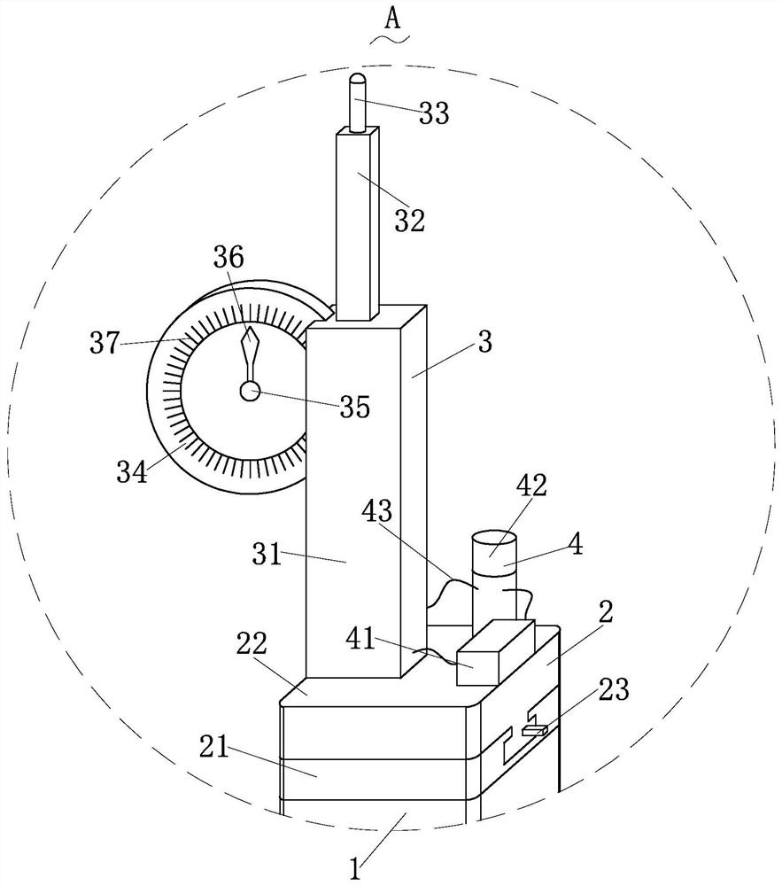
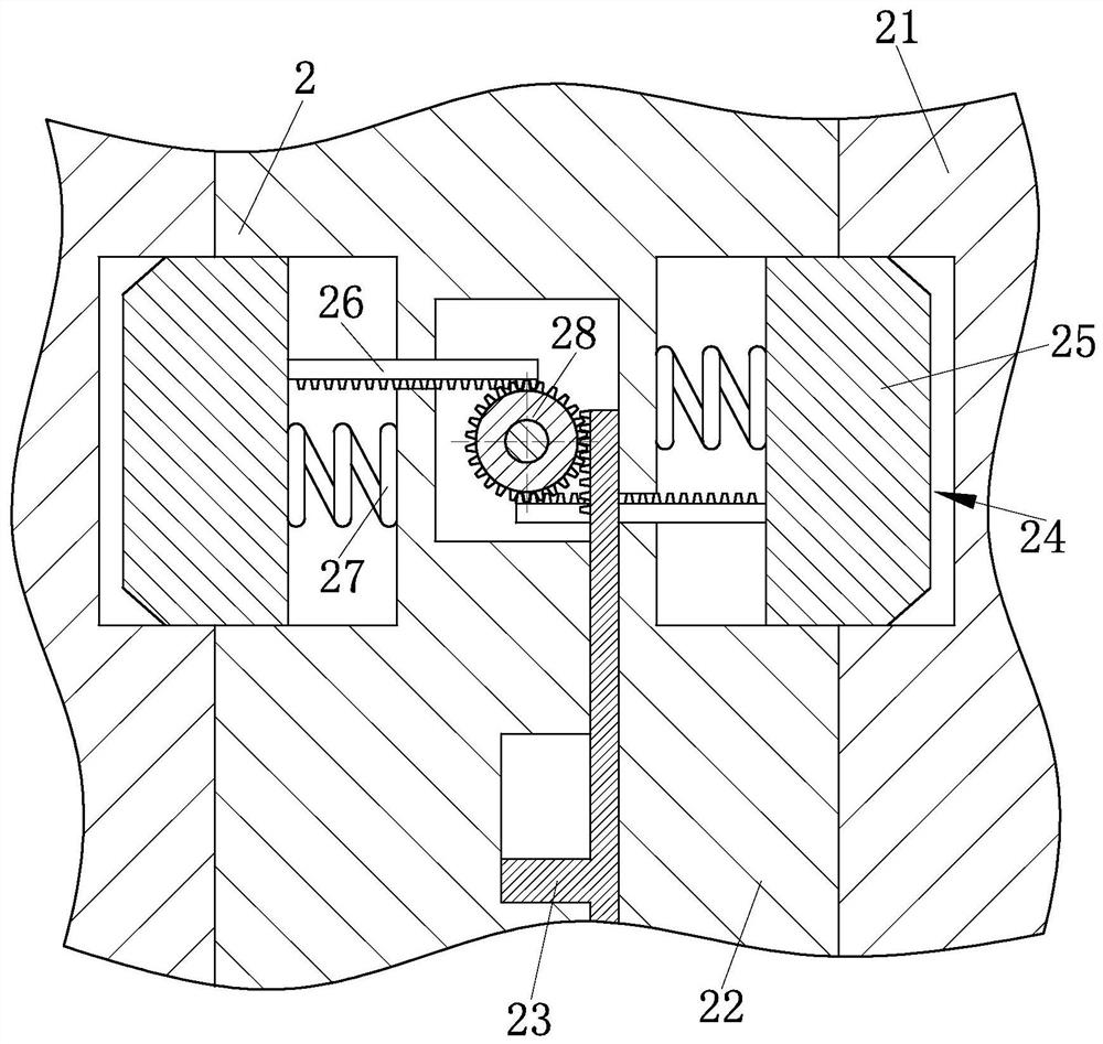
[0029] like Figure 1-Figure 9 As shown, a bridge settlement observation device according to the present invention includes a fixed pipe 1, a connection structure 2, an observation structure 3, an alarm structure 4, an installation structure 5, a limit structure 6 and a support structure 7 for supporting One end of the fixed pipe 1 that is used to install other components is installed with the connecting structure 2 that can quickly connect and fix the observation assembly with the fixed pipe 1, and one end of the connecting structure 2 is provided to monitor the settlement of the bridge. The observation structure 3 that is monitored in time; the alarm structure 4 that can be installed at one end of the connection structure 2 to generate an alarm ...


PUM


Abstract

The invention relates to the field of beam settlement observation equipment, in particular to bridge settlement observation equipment which comprises a fixing pipe, a connecting structure, an observation structure, an alarm structure, a mounting structure, a limiting structure and a supporting structure. Through the arrangement of the observation structure, the settlement condition of the bridge can be accurately observed through a simple structure, so that the settlement value of the bridge can be known in time, the bridge can be maintained in time, the damage condition of the bridge is avoided; and through cooperation with the arrangement of the alarm structure, when the bridge is settled to a preset value, alarm sounds are made timely; and thus the workers are informed of maintenance timely to avoid the bridge collapse risk. The observation assembly and the fixing pipe can be mounted and dismounted quickly and conveniently by arranging the connecting structure between the fixing pipe and the observation structure, so that manpower can be saved, and fixing can be firm. And the mounting structure is arranged, and supporting and fixing of the monitoring assembly can be achieved.

Description

technical field [0001] The invention relates to the field of beam settlement observation equipment, in particular to a bridge settlement observation equipment. Background technique [0002] Bridges generally refer to structures erected on rivers, lakes and seas to allow vehicles and pedestrians to pass smoothly. In order to adapt to the modern high-speed development of the transportation industry, bridges are also extended to buildings that cross mountain streams, poor geology or meet other transportation needs to make traffic more convenient. A bridge is generally composed of a superstructure, a substructure, a support and ancillary structures. The superstructure is also called a bridge span structure, which is the main structure for crossing obstacles; the substructure includes abutments, piers and foundations; Or the force transmission device installed at the supporting place of the bridge abutment; the auxiliary structures refer to the bridge head board, conical slope p...

Claims


Application Information

Patent Timeline
Patent Type & Authority Applications(China)
IPC IPC(8): G01C5/00G01C15/00F16M11/04F16M11/28F16B7/14
CPCF16B7/1454F16M11/04F16M11/28G01C5/00G01C15/00
Inventor 丁启芳
Owner 丁启芳
Learn More