Piezoelectric energy collection device and application and method on floating slab track

A kind of energy harvesting and piezoelectric technology, applied in the direction of piezoelectric effect/electrostrictive or magnetostrictive motors, electrical components, generators/motors, etc., can solve component damage, low bearing capacity, slight shortage, etc. problems, to achieve the effect of increasing output capacity, carrying capacity, and saving vertical space

Active Publication Date: 2020-12-08
CENT SOUTH UNIV
View PDF3 Cites 6 Cited by
  • Summary
  • Abstract
  • Description
  • Claims
  • Application Information

AI Technical Summary

Problems solved by technology

[0006] In the existing research, on the one hand, the power generated by the piezoelectric energy harvesting device is steadily increasing, but it is still slightly insufficient for powering long-term health monitoring systems such as floating plates, mostly less than 100mW
On the other hand, the existing piezoelectric energy harvesting device has a low bearing capacity, and the device with the largest bearing capacity [5] It can only withstand a force of 2.8kN, while the force in the floating plate structure can reach the order of tens of kilonewtons
The existing device is easy to cause damage to parts during use, but it is extremely difficult to replace new parts during railway operation

Method used


Image

  • Piezoelectric energy collection device and application and method on floating slab track
  • Piezoelectric energy collection device and application and method on floating slab track
  • Piezoelectric energy collection device and application and method on floating slab track

Examples


Embodiment 1

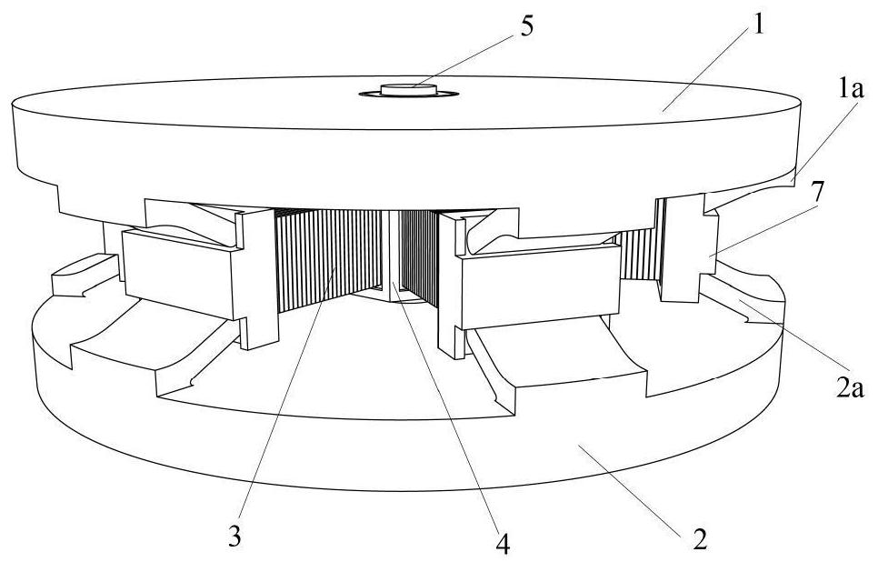
[0063] Such as Figure 3(a) , 3(b) , 4, the piezoelectric energy harvesting device mainly includes the upper cover plate 1, the lower cover plate 2, the pressure plate 7, the piezoelectric ceramic stack 3, the central block 4 and the wires etc., the upper cover plate 1 Between the upper cover plate 1 and the lower cover plate 2, a central block 4 is arranged at the center, and six groups of piezoelectric ceramics arranged radially are arranged symmetrically around the center block 4 between the upper cover plate 1 and the lower cover plate 2. Stack 3, between the upper cover plate 1 and the lower cover plate 2, there is also a device that matches the position and quantity of the piezoelectric ceramic stack 3 and converts the vertical pressure of the upper and lower cover plates 2 into a horizontal thrust in the radial direction. Pushing device, one end of the piezoelectric ceramic stack 3 is supported on the central block 4, and the other end is supported on the pushing devic...

Embodiment 2

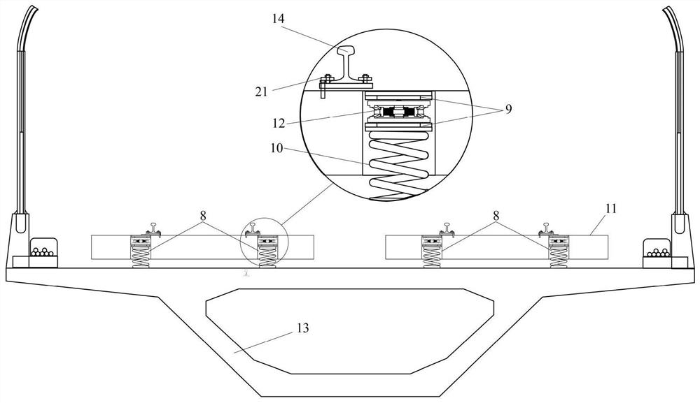
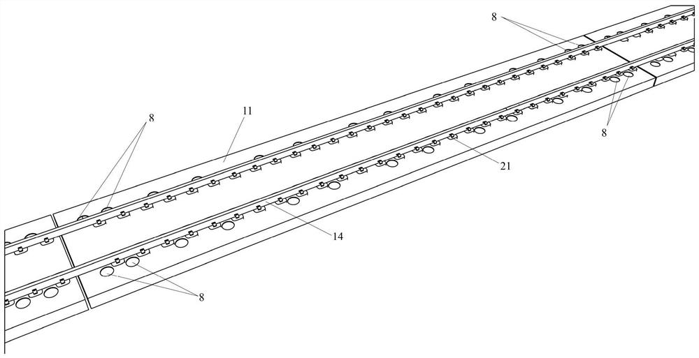
[0066] Such as figure 1 , 2 This embodiment is an application of Embodiment 1. The piezoelectric energy harvesting device is applied to the floating plate track. The floating plate track includes a steel spring floating plate 11, and the steel spring floating plate 11 is equipped with A plurality of steel spring vibration isolators 8, the steel spring vibration isolators 8 include upper and lower backing plates 9 and steel springs 10, the piezoelectric energy harvesting device 12 is arranged in the steel spring vibration isolators 8, the upper and lower backing plates 9, in series with the steel spring.

[0067] The following is a concrete analysis through examples, such as Figure 5 As shown, through analysis, when a B-type subway vehicle passes the floating plate at a constant speed of 120km / h on the main line, the energy harvested by this energy harvesting method from a single steel spring isolator within 5 seconds is 1.07J , the average power is 0.21W, the peak output v...


PUM


Abstract

The invention relates to a piezoelectric energy collection device and an application and method on a floating slab track. The piezoelectric energy collection device comprises an upper cover plate anda lower cover plate, a central block is arranged at the central position between the upper cover plate and the lower cover plate, a plurality of groups of piezoelectric ceramic stacks which are distributed in central symmetry by taking the central block as a center and are distributed along the radial direction are arranged between the upper cover plate and the lower cover plate, one ends of the piezoelectric ceramic stacks are supported on the central block, the other ends are supported on a pushing and pressing device for converting vertical pressure of the upper cover plate and the lower cover plate into radial horizontal thrust, and the floating slab track comprises the piezoelectric energy collecting device arranged in a steel spring vibration isolator. The invention comprises the piezoelectric energy collecting device which is high in bearing capacity, high in output power and low in vertical size. In addition, the piezoelectric energy collecting device is applied to the floatingslab track to form a floating slab track which can provide stable energy and has a safety protection function. The invention further provides a design method of the piezoelectric energy collecting device.

Description

technical field [0001] The invention belongs to the technical field of self-power supply for structure and track health monitoring, and in particular relates to a piezoelectric energy collection device and its application and method on a floating plate track. Background technique [0002] In recent years, steel spring floating slab track has been widely used in urban rail transit because of its obvious vibration reduction effect. However, during the operation process, the concrete floating slab will produce a large vertical displacement, which will lead to fatigue damage of the spring. Therefore, for the safety of railway operation, it is necessary to establish a long-term health monitoring system for the floating slab and the substructure. In this way, the vertical displacement and service status of the steel spring are continuously monitored. However, this long-term health monitoring system requires power supply, and how to provide long-term power supply for these health ...

Claims


Application Information

Patent Timeline
Patent Type & Authority Applications(China)
IPC IPC(8): H02N2/18
CPCH02N2/181H02N2/186
Inventor 侯文崎郑勇袁义华国巍郭鹏程
Owner CENT SOUTH UNIV
Why Eureka
Try Eureka