Outdoor camera for community electronic monitoring

An electronic monitoring and camera technology, applied in the direction of TV, electrical components, color TV, etc., can solve the problems of aging, camera damage, shorten the service life, etc., and achieve the effect of slowing down the aging speed, reducing the impact and prolonging the service life.

Inactive Publication Date: 2020-12-08
李云生
View PDF1 Cites 2 Cited by
  • Summary
  • Abstract
  • Description
  • Claims
  • Application Information

AI Technical Summary

Problems solved by technology

[0003] Existing patent (notification number: CN210007784U) discloses a kind of community electronic monitoring user's outdoor camera, comprises box door, and the front of described box door is provided with observation opening, and the inner wall of described observation opening is fixedly connected with light-transmitting lens, and described The front of the box door is provided with an air vent, the inner wall of the air vent is fixedly connected with a baffle, the inner wall of the air vent is fixedly connected with a dust-proof net, one side of the box door is fixedly connected with a connecting block, and the connection The outer wall of the block is fixedly connected with a block; the inventors have found that at least the following problems have not been solved in the prior art: 1. The outdoor camera used for electronic monitoring in this community is susceptible to rapid aging due to sunlight and shortens the service life; 2. The electronic monitoring of the community uses an outdoor camera, and the high outdoor temperature may easily cause the camera to be damaged by the high temperature

Method used


Image

  • Outdoor camera for community electronic monitoring
  • Outdoor camera for community electronic monitoring
  • Outdoor camera for community electronic monitoring

Examples


Embodiment Construction

[0024] In order to make the technical means, creative features, goals and effects achieved by the present invention easy to understand, the present invention will be further described below in conjunction with specific embodiments.

[0025] In the description of the present invention, it should be noted that the terms "upper", "lower", "inner", "outer", "front end", "rear end", "both ends", "one end", "another end" The orientation or positional relationship indicated by etc. is based on the orientation or positional relationship shown in the drawings, and is only for the convenience of describing the present invention and simplifying the description, rather than indicating or implying that the referred device or element must have a specific orientation, use a specific Azimuth configuration and operation, therefore, should not be construed as limiting the invention. In addition, the terms "first" and "second" are used for descriptive purposes only, and should not be understood ...


PUM


Abstract

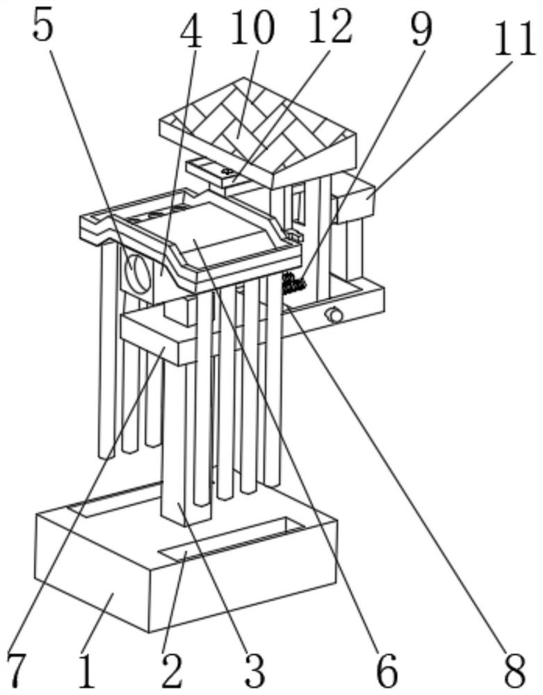
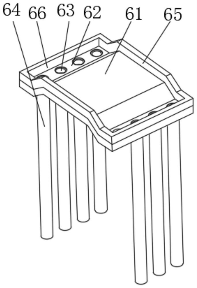
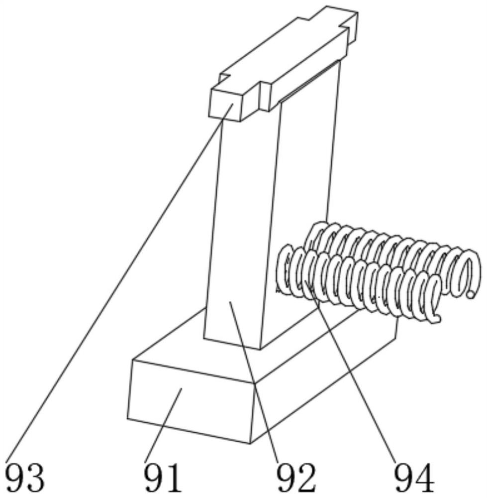
The invention discloses a community electronic monitoring outdoor camera which comprises a placement table, the front portion and the rear portion of the upper end of the placement table are each provided with a placement groove, a supporting column is fixedly installed in the middle of the upper end of the placement table, a monitor is fixedly installed at the upper end of the supporting column,and a camera body is fixedly installed at the left end of the monitor. A sunshade drainage device is arranged at the upper end of the monitor, a supporting plate is fixedly installed on the upper portion of the outer surface of the supporting column, a through groove is formed in the right portion of the upper end of the supporting plate, a magnetic device is arranged on the left portion of the groove wall of the through groove, and an energy supply device is arranged in the middle of the groove wall of the through groove. An expansion device is arranged on the right portion of the upper end of the supporting plate, and a water storage device is arranged on the upper portion of the left end of the energy supply device. According to the outdoor camera for community electronic monitoring, the solar panel can absorb sunlight, so that sunlight is prevented from directly irradiating the surface of the monitor, the aging speed of the monitor is reduced, and the service life of the monitor isprolonged.

Description

technical field [0001] The invention relates to the field of camera equipment, in particular to an outdoor camera for residential electronic monitoring. Background technique [0002] The camera can be divided into two categories: digital camera and analog camera. The digital camera can convert the analog video signal generated by the video capture device into a digital signal, and then store it in the computer. The video signal captured by the analog camera must pass through a specific video The capture card converts the analog signal into a digital mode, and compresses it before converting it to the computer for use. The digital camera can directly capture the image, and then pass it to the computer through a serial, parallel or USB interface. [0003] Existing patent (notification number: CN210007784U) discloses a kind of community electronic monitoring user's outdoor camera, comprises box door, and the front of described box door is provided with observation opening, and ...

Claims


Application Information

Patent Timeline
Patent Type & Authority Applications(China)
IPC IPC(8): H04N5/225G03B17/55
CPCG03B17/55H04N23/51
Inventor 李云生
Owner 李云生
Why Eureka
Try Eureka