Supercharge Your Innovation With Domain-Expert AI Agents!

A movable position platform for large wind power castings

A large-scale casting, movable technology, applied in the direction of molding table, molding machine, casting and molding equipment, etc., can solve the problem of difficult positioning of large-scale casting molds.

Active Publication Date: 2022-04-12
山东国创精密机械有限公司
View PDF0 Cites 0 Cited by
  • Summary
  • Abstract
  • Description
  • Claims
  • Application Information

AI Technical Summary

Problems solved by technology

[0005] On the one hand, in order to solve the above-mentioned technical problem that the large-scale casting mold is not easy to locate on the micro-seismic support and the micro-seismic table, the technical solution adopted is: a movable position platform for large-scale wind power castings, including the micro-seismic support and mobile Claws, the moving claws are located on the upper part of the microseismic support and can move forward, backward, left, and right on the microseismic support to clamp and position large castings; the microseismic support is equipped with a two-way worm, and the two-way worm has a forward rotation section and a reverse rotation section. The rotation section is connected with a worm gear matched with the forward rotation section and the reverse rotation section. The worm gear is equipped with a centering clamping mechanism, and the forward rotation section and the reverse rotation section can be rotated by turning the worm. The two worm gears on the section drive two centering clamping mechanisms installed on the worm gears to move toward each other; the centering clamping mechanism includes a two-way screw, a nut block and a connecting piece, and the two ends of the two-way screw pass through the connecting piece Being installed on the worm wheel can make the two-way screw move with the worm wheel but not rotate with the worm wheel. There are two nut blocks and these two nut blocks are respectively installed on the screws of the opposite direction of the two-way screw. Each nut block corresponds to a moving card. jaw and the mobile jaw is firmly attached to the nut block

Method used


Image

  • A movable position platform for large wind power castings
  • A movable position platform for large wind power castings
  • A movable position platform for large wind power castings

Examples


specific Embodiment approach 1

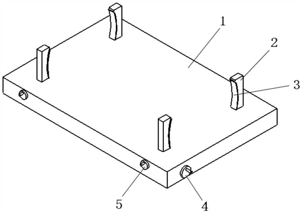
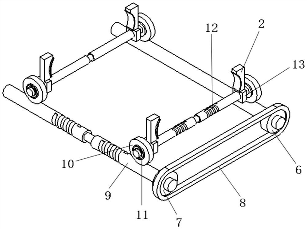
[0024] Such as Figure 1 to 3 As shown, the present invention provides a moving position platform of a wind power large-scale casting, including a microseisman bracket 1, and a moving jaw 2, and the moving jaw 2 is located at the upper portion of the microseisman bracket 1 and can be moved before the micro-shock bracket 1. A large casting clamping; two-way worm 9 is mounted on the microseisman bracket 1, the bidirectional worm 9 has a positive rotation segment and a reverse rotation direction, and there is a connection on the routing segment and the reflection section. The adapted worm wheel 10 is mounted on the worm wheel 10, and the two worm gear 10 on the positive rotation section and the reflection section can be driven by the rotating worm 9 to drive two pairs mounted on the worm wheel 10. The clamping mechanism is inverted; the pairing clamping mechanism includes a bidirectional screw 12, a nut block, and a connecting member 11, the connecting member 11 being a bearing, and t...

specific Embodiment approach 2

[0028] This specific embodiment is different from the specific embodiment 1: The bidirectional worm 9 is provided with a bidirectional worm 9 located in the intermediate position of the bidirectional screw 12, the worm wheel 10 mounted in the middle of the bidirectional screw 12, the chormhing and the front and rear The worm wheel 10 on the root bidirectional screw 12 is driven, and a first hand wheel 4 is connected to the worm, the first hand wheel 4 located outside the microseisman bracket 1.

specific Embodiment approach 3

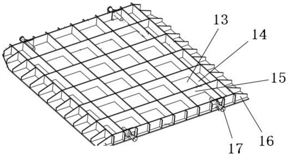
[0029] Such as image 3 As shown, the specific embodiment is improved on the basis of the specific embodiment 1 or 2, the improvement point is that the microseisman bracket 1 includes a soldering fixed on a piece of bottom plate 13, a lateral steel plate 15, and a longitudinal steel plate 14, which is said. A checker is formed between the lateral steel plate 15 and the longitudinal steel plate 14, the lateral steel plate 15 and the tip end of the longitudinal steel sheet 14, and supports a reinforcing rib 16 on the outer longitudinal steel plate 14, and the upper portion of the rib 16 is supported. In order to incline the downward, the slope is lower than the placement surface. The microseisman bracket 1 is welded in transverse, longitudinally thick high-strength steel sheet to ensure the strength of the microseisman bracket 1, the bottom is consistent with the micro-resistance space, the upper portion is consistent with the mold size, ensuring the load-bearing effect, and there is...


PUM


Abstract

The present invention provides a movable position platform for large wind power castings. The solution adopted is to include a microseismic support, and a two-way worm is installed on the microseismic support. The two-way worm has a forward rotation section and a reverse rotation section. The rotation section and the anti-rotation section are each connected with a turbine adapted to it, and a centering clamping mechanism is installed on the turbine, and the centering clamping mechanism includes a two-way screw, a nut block and a connecting piece. The two-way screw is installed on the turbine through the connecting piece so that the two-way screw moves with the turbine but does not rotate with the turbine. The nut block is provided with two and these two nut blocks are respectively installed on the screws of the opposite direction of the two-way nut. The nut The blocks are fixedly connected to the moving jaws. Realize the movement of large castings with the microseismic support to meet the positioning requirements, and can avoid the collision of large castings caused by the movement of the microseismic support to cause damage to itself or damage to the mold plate.

Description

Technical field [0001] The present invention relates to the field of large castings, and more particularly to a moving position platform for wind power large castings. Background technique [0002] In order to ensure the tightness of sand, the current large wind power castings need to be micrographed during shape. Typically, the micro-resistance station is flush with the shape of the styling pit. For large wind power castings, the size of its mold is large, and the support is required to support it on the micro-resistance station, but because the microstrictive bracket is not effective, the micro-earthquake station is up and down. When the left and right vibration, it is easy to damage the mold plate; and due to large mold size, weight is heavy, it is easy to alias when placed, and it is difficult to act after the micro-shock bracket and the micro-shock station. Leading normal production delays, the production efficiency has fallen sharply; and the cost of mold maintenance has in...

Claims


Application Information

Patent Timeline
Patent Type & Authority Patents(China)
IPC IPC(8): B22C19/02B22C15/10
CPCB22C19/02B22C15/10
Inventor 樊青峰时伟
Owner 山东国创精密机械有限公司
Features
  • R&D
  • Intellectual Property
  • Life Sciences
  • Materials
  • Tech Scout
  • Unparalleled Data Quality
  • Higher Quality Content
  • 60% Fewer Hallucinations
Learn More