Clamp for machining hydraulic valve block datum plane

A technology of hydraulic valves and reference surfaces, which is applied in the field of hydraulic parts processing, and can solve the problem that fixtures cannot be reused

Active Publication Date: 2020-11-03
HANDAN HENGGONG METALLURGICAL MACHINERY CO LTD
View PDF13 Cites 0 Cited by
  • Summary
  • Abstract
  • Description
  • Claims
  • Application Information

AI Technical Summary

Problems solved by technology

[0003] The invention provides a fixture for processing the reference plane of a hydraulic valve block to solve the problem that the existing fixture cannot be reused

Method used


Image

  • Clamp for machining hydraulic valve block datum plane
  • Clamp for machining hydraulic valve block datum plane
  • Clamp for machining hydraulic valve block datum plane

Examples


Embodiment 1

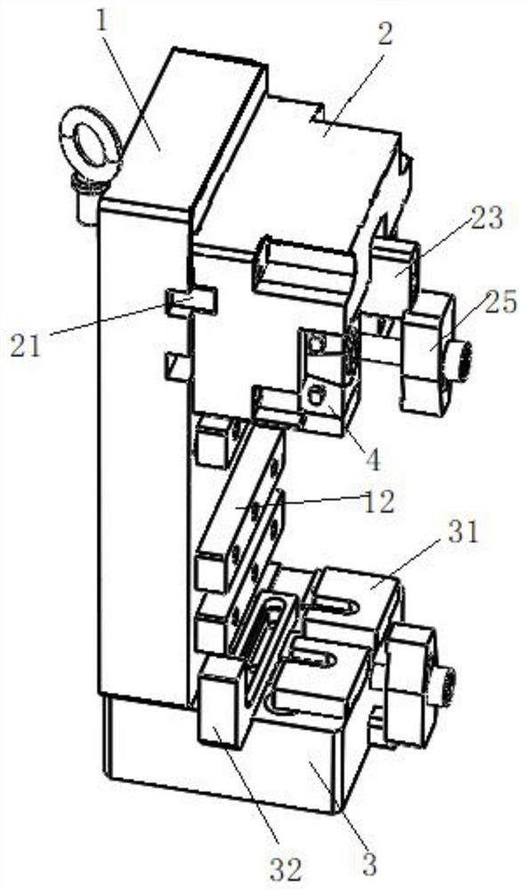
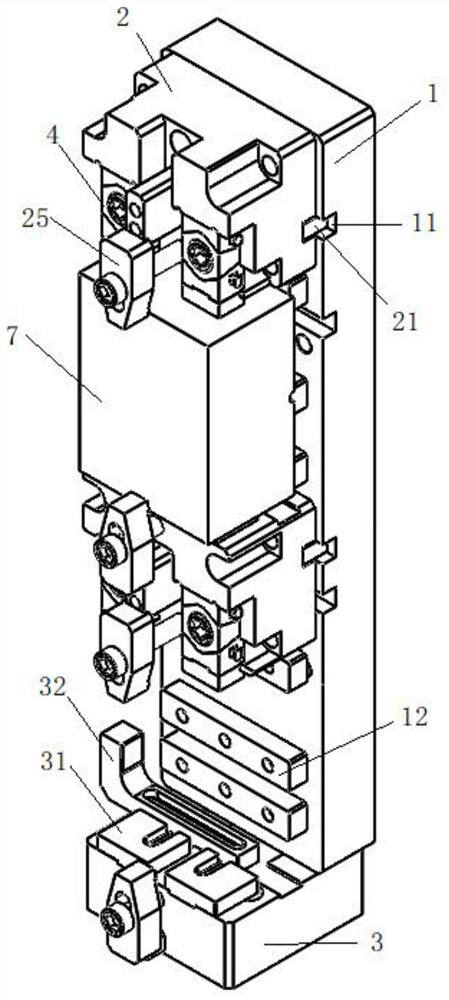
[0035] Embodiment 1: as figure 1 as well as Figure 4-8 As shown, including the vertical plate 1, the upper and lower ends of the vertical plate 1 are respectively fixed with a compression seat 2 and a positioning seat 3, and two adjustment grooves 11 are formed on one side of the vertical plate 1, and the vertical plate 1 is connected with the pressure by the adjustment groove 11. The tight seat 2 is clamped, and the surroundings are tightened by screws.

[0036] like figure 1 , Upper positioning: The side of the pressing seat 2 close to the vertical plate 1 is provided with a block 21 that matches the adjustment groove 11 .

[0037] In the process of processing, the faces of some hydraulic valve blocks 7 are non-parallel faces, and the existing clamps cannot clamp the non-parallel faces. Therefore, the present invention forms slide grooves at the two ends on the other side of the pressing seat 2. 22. A micro-adjustment mechanism 4 is slidably connected in the chute 22, an...

Embodiment 2

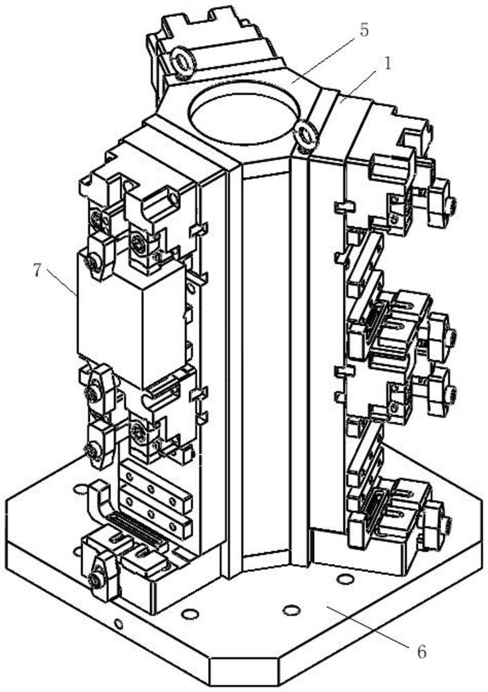
[0044] Embodiment 2: as figure 2 , 3 As shown, a fixture for processing the reference plane of the hydraulic valve block can clamp six hydraulic valve blocks 7 at one time, including the support column 5 and the bottom plate 6 arranged perpendicular to each other. The support column 5 is a regular hexagonal prism to avoid Interference, three vertical plates 1 are distributed on the side of the regular hexagonal prism at intervals, and one side of the vertical plate 1 is fixed on the support column 5. On the basis of embodiment 1, this embodiment is based on the compression seat 2 and the positioning seat 3. A pressing seat 2 is added in the middle, and an adjustment groove 11 and a second positioning block 12 are correspondingly added to the vertical plate 1. The above structure can process the upper and lower hydraulic valve blocks 7 at the same time, saving the time required for processing and reducing the cost. A first positioning block 31 is respectively fixed on both en...


PUM


Abstract

The invention discloses a clamp for machining a hydraulic valve block datum plane. The clamp comprises a vertical plate, a pressing base and a positioning base, the pressing base and the positioning base are oppositely arranged, the vertical plate is detachably connected with the pressing base through an adjusting groove, a clamping block matched with the adjusting groove is arranged at the side,close to the vertical plate, of the pressing base, at least one sliding groove is formed at the other side, and a fine adjustment mechanism is slidably connected into the sliding groove. At least onefirst positioning block is arranged at the end, away from the vertical plate, of the positioning base. A space for fixing a hydraulic valve block is formed when the vertical plate, the pressing base,the positioning base and the fine adjustment mechanism are connected. The clamp is suitable for machining hydraulic valve blocks of certain specifications and models, the machining efficiency is improved, and the production cost is reduced.

Description

technical field [0001] The invention relates to the technical field of hydraulic parts processing, in particular to a fixture used for processing the datum plane of a hydraulic valve block. Background technique [0002] In the production process of the hydraulic valve, in order to ensure the matching accuracy between the hydraulic valve block and the valve core, the hydraulic valve block must be positioned when processing the reference plane of the hydraulic valve block. There are many types of valve blocks, and most of the existing valve block fixtures are used for a single type, which cannot be reused, resulting in high cost. Contents of the invention [0003] The invention provides a fixture used for processing the datum plane of a hydraulic valve block to solve the problem that the existing fixture cannot be reused. [0004] This application includes: [0005] A fixture for processing the reference plane of a hydraulic valve block, including a vertical plate and a pr...

Claims


Application Information

Patent Timeline
Patent Type & Authority Applications(China)
IPC IPC(8): B23Q3/08
CPCB23Q3/082
Inventor 魏志勇高运强孔令伟
Owner HANDAN HENGGONG METALLURGICAL MACHINERY CO LTD
Why Eureka
Try Eureka