Supercharge Your Innovation With Domain-Expert AI Agents!

Automatic discharging circular plate cutting device adopting grooved wheel transmission

A technology of automatic unloading and sheave drive, applied in metal processing and other directions, can solve the problems of low cutting efficiency of circular plates, effective cutting range, increase processing cost, etc., to improve the use range, reduce work difficulty, and increase work efficiency. Effect

Active Publication Date: 2020-12-11
临沂利金木业有限公司
View PDF0 Cites 2 Cited by
  • Summary
  • Abstract
  • Description
  • Claims
  • Application Information

AI Technical Summary

Problems solved by technology

[0002] Plate cutting refers to a cutting process for various plate-shaped profiles. For plates of different materials and shapes, different types and specifications of cutting devices are often required. Among them, for the cutting of round plates, the existing cutting device It is usually cut by a circular hollow cutting knife. After the cutting is completed, the circular plate needs to be manually unloaded, resulting in low cutting efficiency and high processing difficulty for the existing circular plate. At the same time, during the cutting process of the circular plate, For circular plates with different diameters, it is often necessary to configure new cutting blades, resulting in the effective cutting range of existing cutting devices and increasing processing costs

Method used


Image

  • Automatic discharging circular plate cutting device adopting grooved wheel transmission
  • Automatic discharging circular plate cutting device adopting grooved wheel transmission
  • Automatic discharging circular plate cutting device adopting grooved wheel transmission

Examples


Embodiment Construction

[0028] The following will clearly and completely describe the technical solutions in the embodiments of the present invention with reference to the accompanying drawings in the embodiments of the present invention. Obviously, the described embodiments are only some, not all, embodiments of the present invention. Based on the embodiments of the present invention, all other embodiments obtained by persons of ordinary skill in the art without making creative efforts belong to the protection scope of the present invention.

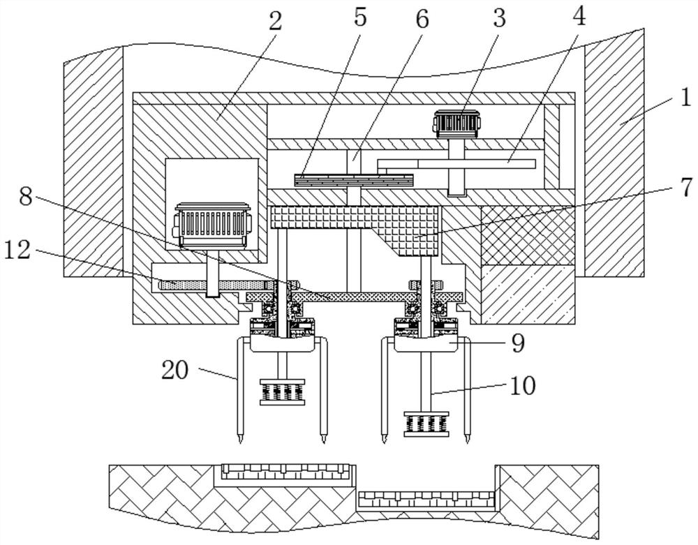
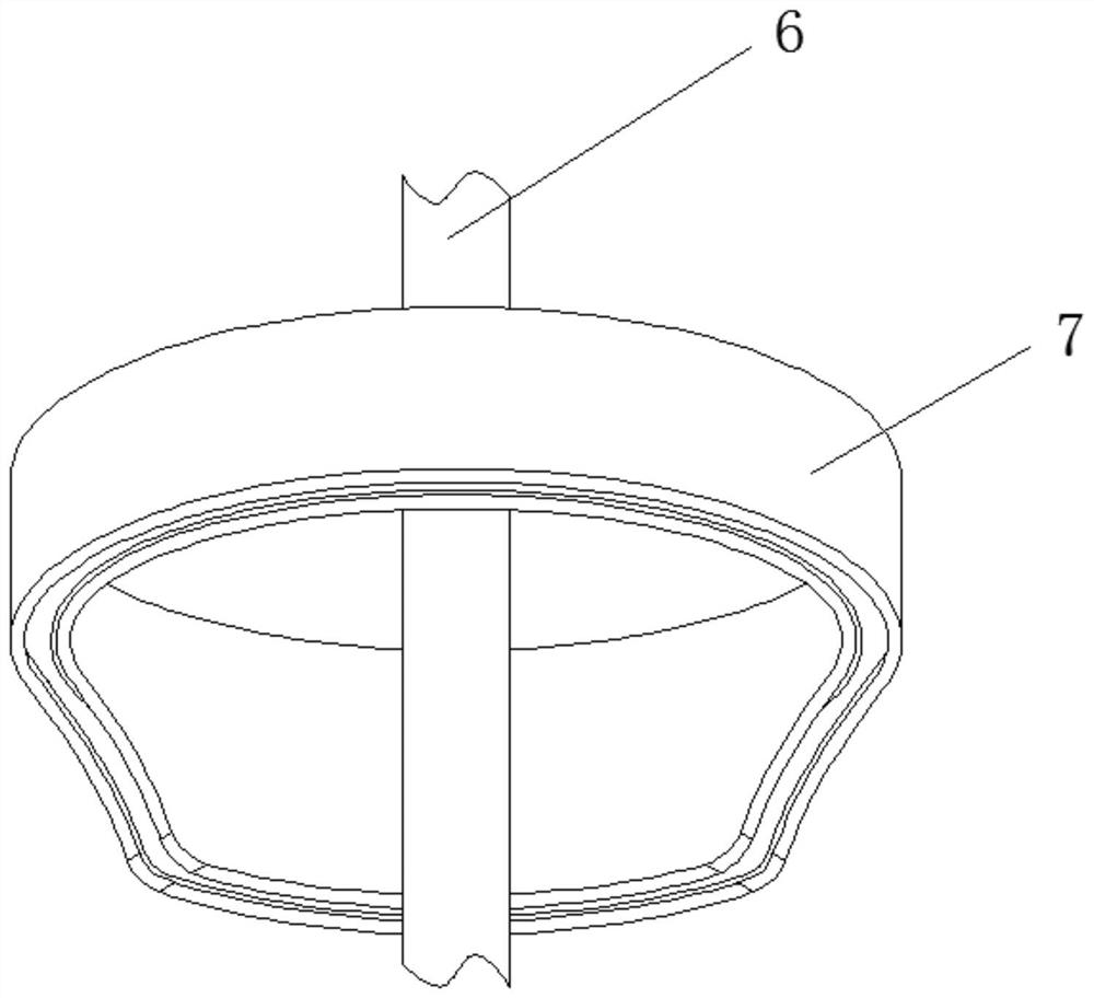
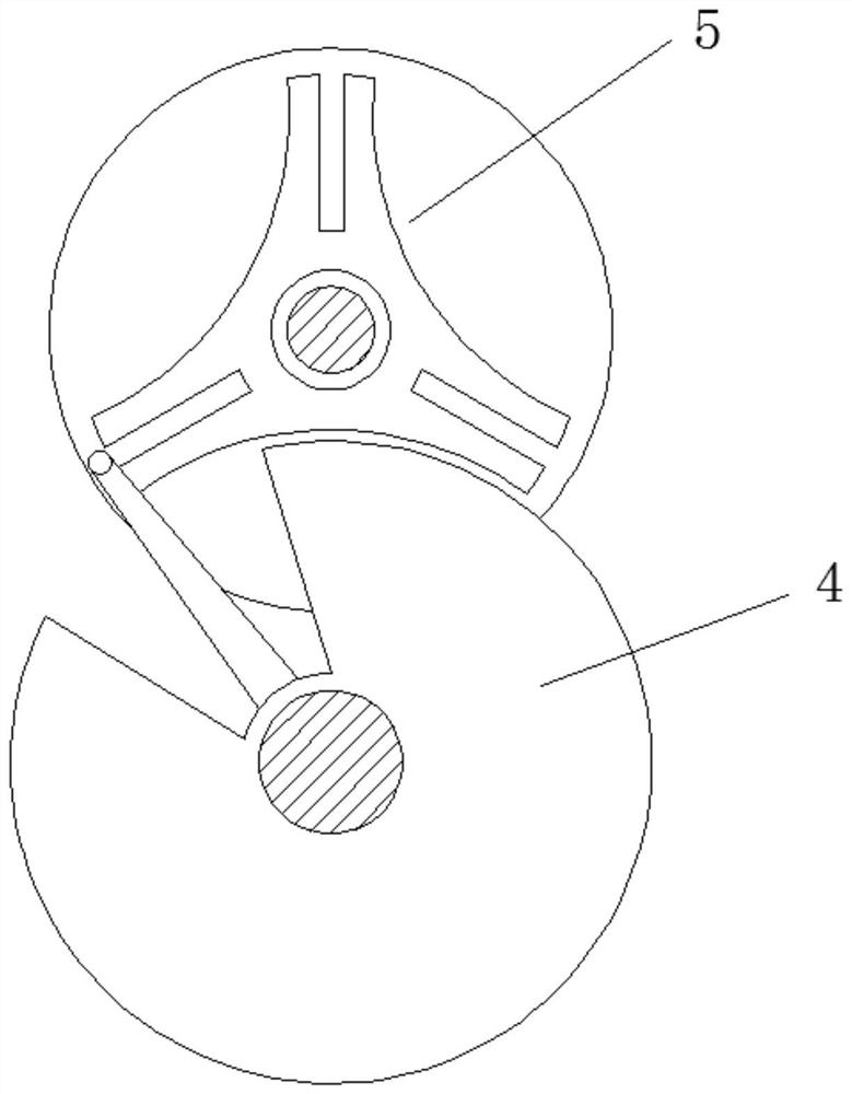
[0029] see Figure 1-6 , an automatic unloading circular plate cutting device driven by a grooved wheel, including a frame 1, a lifting seat 2, an unloading motor 3, a dial wheel 4, a grooved wheel 5, an adjustment rod 6, a convex ring 7, and a support plate 8. Positioning block 9, ejector rod 10, cutting gear 11, main gear 12, adjusting worm 13, adjusting gear 14, flat gear ring 15, feed gear 16, feed rod 17, gear rod 18, push block 19, cutting Knife 20.

...


PUM


Abstract

The invention relates to the technical field of plate cutting, and discloses an automatic discharging circular plate cutting device adopting grooved wheel transmission. The automatic discharging circular plate cutting device comprises a rack, a lifting seat is movably connected to the interior of the rack, a discharging motor is fixedly connected to the interior of the lifting seat, and a thumb wheel is fixedly connected to the bottom of the discharging motor; and a grooved wheel is movably connected to the exterior of the thumb wheel, an adjusting rod is fixedly connected to the interior of the grooved wheel, a convex ring is fixedly connected to the exterior of the adjusting rod, a supporting disc is fixedly connected to the bottom of the adjusting rod, a positioning block is rotatably connected to the bottom of the supporting disc, and a jacking rod is movably connected to the interior of the positioning block. Through cooperative use of an adjusting worm, an adjusting gear, a flatgear ring, a feeding gear, a feeding rod, a gear rod and a push block, cutting machining of circular plates with different diameters is conveniently met, the use range of the automatic discharging circular plate cutting device is effectively extended, the use effect is improved, preparation of tools with different specifications is reduced, and thus the production cost is reduced.

Description

technical field [0001] The invention relates to the technical field of plate cutting, in particular to an automatic unloading circular plate cutting device driven by a groove wheel. Background technique [0002] Plate cutting refers to a cutting process for various plate-shaped profiles. For plates of different materials and shapes, different types and specifications of cutting devices are often required. Among them, for the cutting of round plates, the existing cutting device It is usually cut by a circular hollow cutting knife. After the cutting is completed, the circular plate needs to be manually unloaded, resulting in low cutting efficiency and high processing difficulty for the existing circular plate. At the same time, during the cutting process of the circular plate, For circular plates with different diameters, it is often necessary to configure new cutting blades, resulting in an effective cutting range of the existing cutting device and increasing the processing c...

Claims


Application Information

Patent Timeline
IPC IPC(8): B26D1/43B26D5/08B26D7/26B26D7/32
CPCB26D1/43B26D5/086B26D7/2628B26D7/32
Inventor 王高锋
Owner 临沂利金木业有限公司
Features
  • R&D
  • Intellectual Property
  • Life Sciences
  • Materials
  • Tech Scout
  • Unparalleled Data Quality
  • Higher Quality Content
  • 60% Fewer Hallucinations
Learn More