[0023] The technical solutions in the embodiments of the present invention will be clearly and completely described below with reference to the accompanying drawings in the embodiments of the present invention. Obviously, the described embodiments are only a part of the embodiments of the present invention, rather than all the embodiments. Based on the embodiments of the present invention, all other embodiments obtained by those of ordinary skill in the art without creative efforts shall fall within the protection scope of the present invention.
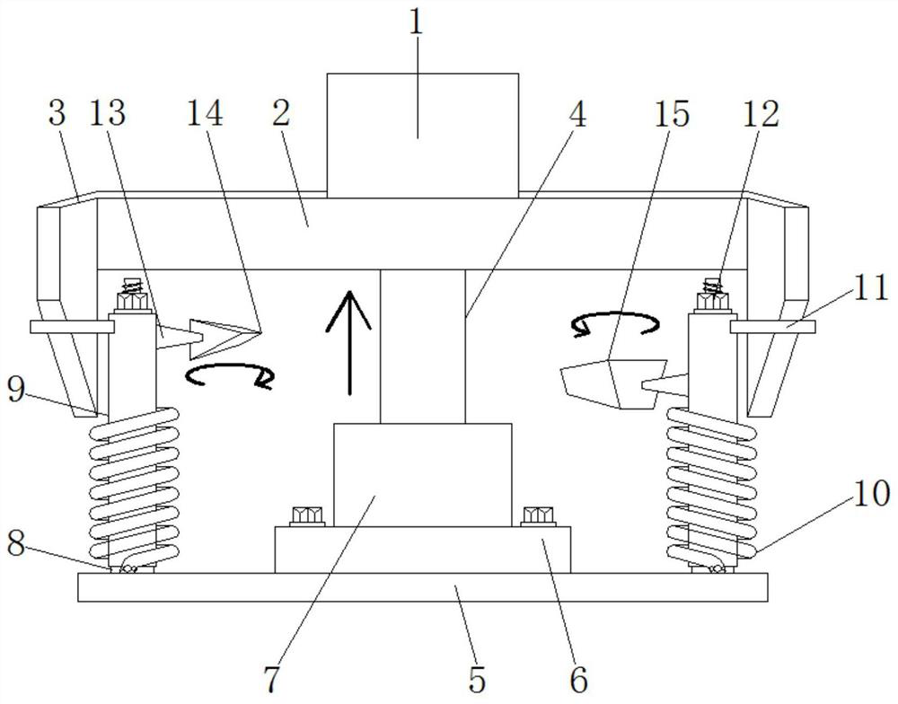
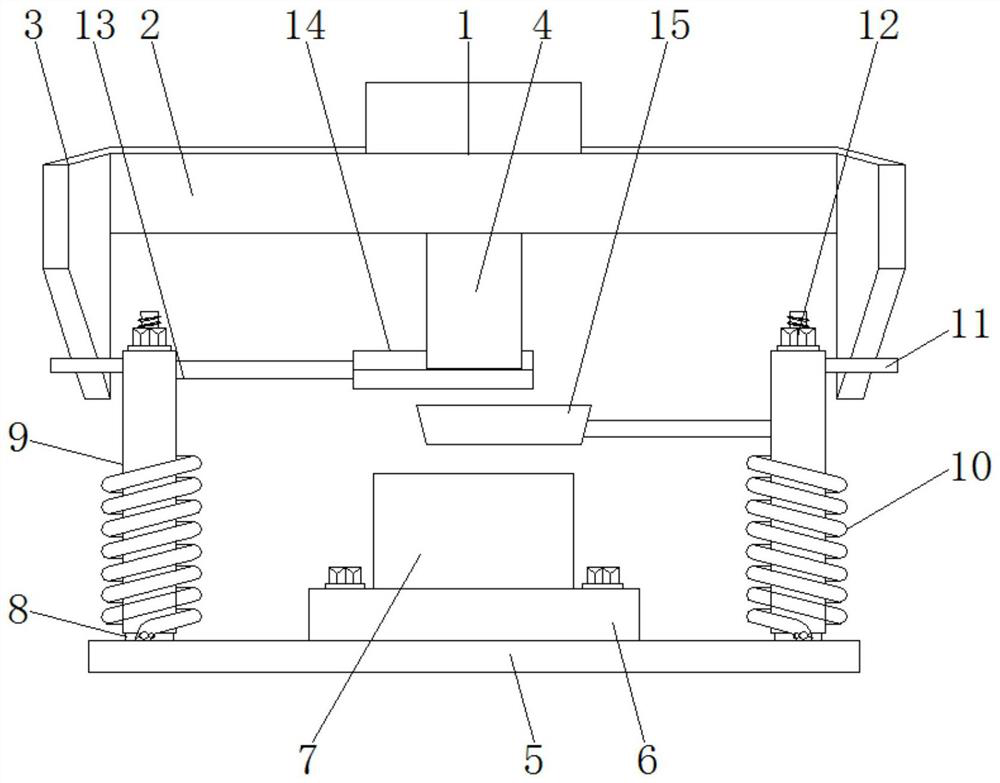
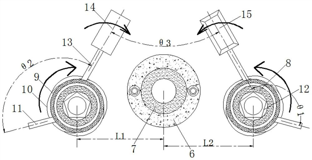
[0024] see Figure 1-5 , an intelligent separation and collection mechanism of punch waste for plastic product processing, comprising a lowering table 1 and a base 5, a pressing plate 2 is fixedly installed at the bottom end of the lowering table 1, and a driving block 3 is fixedly installed on the outer side of the pressing plate 2, and the driving blocks 3 are arranged in total There are two with the same size and size. They are located on both sides of the pressure plate 2 and are perpendicular to the pressure plate 2. The drive block 3 is a right-angled trapezoid. In this way, when the descending table 1 moves up and down, the hypotenuse can be driven to move, thereby driving the rotation of the driving rod 11. The bottom end of the pressure plate 2 is fixedly installed with the upper module 4, and the top of the base 5 is fixedly installed with a positioning plate 6. The positioning plate 6 It is cylindrical, the bottom end is fixedly connected with the base 5, the top end is fixedly connected with the lower module 7, nuts are provided on both sides, the upper end of the positioning plate 6 is fixedly installed with the lower module 7, and the lower module 7 is cylindrical and is the same as the positioning plate 6. The size of the axis is smaller than that of the positioning plate 6, and a hole is opened inside and the size of the hole is adapted to the size of the upper module 4. The upper module 4 is used in conjunction with the hole opened in the lower module 7 to realize the adjustment of the product size, so as to achieve the desired processing efficiency. accuracy and efficiency;
[0025] The upper end of the base 5 is fixedly installed with a positioning rod 8, the outer side of the positioning rod 8 is sleeved with a rotation rod 9, and the outer side of the rotation rod 9 is sleeved with a return spring 10, the positioning rod 8, the rotation rod 9, and the return spring 10 are provided with two They are divided into two groups with the same size and size, which are symmetrically distributed on the inner side of the drive blocks 3 on both sides of the lower module 7, wherein the distance between the left positioning rod 8 and the lower module 7 is L1, and the right positioning rod 8 and the lower The distance between the modules 7 is L2, the return spring 10 can realize the rotation of the rotating rod 9 when the descending table 1 rises, and play a good role in limiting and adjusting. There are two driving rods 11 with the same size and size, which are symmetrically distributed on the outside of the two rotating rods 9, and the other end is movably connected with the oblique side of the driving block 3. A fixed rod 13 is fixedly installed on the outer side, and a conical shovel 14 is fixedly installed at one end of the fixed rod 13 away from the rotating rod 9. After the stamping is completed, the upper module 4 moves upward, and the conical shovel 14 is driven by the driving rod 11. Rotate in 4 directions, when the conical shovel 14 reaches the upper module position, it just contacts the bottom of the upper module 4, and the scraps adhered to the bottom of the upper module 4 are separated. , greatly improving the degree of intelligence of the equipment; the end of the fixed rod 13 away from the rotating rod 9 is fixedly installed with a storage tank 15 , and there are two fixed rods 13 with the same size and size, which are respectively located on the inner side of the two rotating rods 9 , the angle between the left side and the driving rod 11 is θ2, the angle between the right side and the driving rod 11 is θ1, the left side is higher than the right fixing rod 13, and the other end of the left fixing rod 13 is the same as the tapered The shovel 14 is fixedly connected, the other end of the right fixing rod 13 is fixedly connected to the storage tank 15, the angle between the conical shovel 14 and the storage tank 15 is θ3, and manual cleaning is not required during the process, saving time and effort, and avoiding the possibility of The damage to personnel occurs, and the work efficiency during processing is improved at the same time. When the waste is detached, there is a storage tank 15 below to collect the waste, so as to prevent the drop of the waste from affecting the quality of the next processed product, and improve the quality of the next processed product to a certain extent. the quality of the product.
[0026] Working principle: After the equipment completes stamping, the descending table 1 rises. Since the bottom end of the descending table 1 is fixedly installed with the pressure plate 2, the two sides of the pressure plate 2 are fixedly installed with the driving block 3 in the vertical direction of the pressure plate 2, that is, the rising of the descending table 1 drives the The driving block 3 rises, and the contact edge between the driving block 3 and the driving rod 11 is a hypotenuse, the rotating rod 9 is sleeved on the outside of the positioning rod 8, and the outside of the rotating rod 9 is sleeved with a return spring 10 and the upper end of the spring is connected to the rotating rod 9. Fixed connection, the lower end is fixedly connected to the outside of the positioning rod 8, that is, the driving rod 11 is rotated under the combined action of the return spring 10 and the driving rod 11. When the bottom of the upper module 4 rises to the same height as the conical shovel 14, at this time The conical shovel 14 is just in contact with the bottom of the upper module 4. If there is waste adhering to the bottom of the upper module 4, the waste should be removed in time. Since the storage tank 15 is located below the conical shovel 14 and moves upwards to the bottom of the module 4 in synchronization with the conical shovel 14 Rotation, that is, the scraps removed by the conical shovel 14 fall into the storage tank 15 , thereby preventing the scraps from falling into the lower module 7 .
[0027] To sum up, the waste of the punch press for processing plastic products is intelligently separated from the collection mechanism. After the punching is completed, the upper module 4 moves upward, and the conical shovel 14 automatically rotates in the direction of the upper module 4 under the driving of the driving rod 11. When the conical shovel 14 When it reaches the position of the upper module 4, it just contacts the bottom of the upper module 4, and the scraps adhered to the bottom of the upper module 4 are detached. The whole process is under normal working conditions, avoiding the shutdown for manual detachment, and greatly improving the intelligence of the equipment degree of transformation.
[0028] The punch waste for plastic product processing is intelligently separated from the collection mechanism, and no manual cleaning is required in the process, which saves time and effort, avoids possible personnel damage, and improves the work efficiency during processing. The trough 15 collects the waste material, prevents the waste material from falling and affects the quality of the next processed product, and improves the quality of the product to a certain extent.
[0029] Although embodiments of the present invention have been shown and described, it will be understood by those skilled in the art that various changes, modifications, and substitutions can be made in these embodiments without departing from the principle and spirit of the invention and modifications, the scope of the present invention is defined by the appended claims and their equivalents.