
A power transmission system of a reel type sprinkler irrigation machine and its working method

A power transmission system and working method technology, applied in the direction of non-mechanical drive clutches, botanical equipment and methods, mechanical equipment, etc., can solve problems affecting the accuracy of mechanism movements, complex gearbox structures, and complex overall structures, and achieve reliable High reliability, high degree of automation, and cost reduction

Inactive Publication Date: 2018-11-09
CHINA UNIV OF MINING & TECH
View PDF11 Cites 0 Cited by
  • Summary
  • Abstract
  • Description
  • Claims
  • Application Information

AI Technical Summary

Problems solved by technology

[0003] The water turbine currently used causes a large pressure drop, high energy consumption, and low efficiency, so a high-power water pump needs to be selected as the power source; at the same time, the existing reel sprinkler irrigation machine speed control system is a set of connecting rod mechanism, through the connecting rod mechanism The speed of the water turbine is controlled by controlling the opening of the tongue of the water turbine. The structure is complex and the control accuracy is low; and the meshing and disconnection of the sliding gears are controlled through the gear release mechanism in the gearbox, and the cutting and closing of the power is controlled, which is convenient for the sprinkler truck. release and recovery, but this makes the structure of the gearbox complex, high in cost, and large in overall size; although the existing sprinkler can use a set of linkage mechanisms to achieve speed regulation and off-gear, the overall structure is complex, and it will affect the action of the mechanism after long-term use accuracy, poor reliability

Method used


Image

  • A power transmission system of a reel type sprinkler irrigation machine and its working method
  • A power transmission system of a reel type sprinkler irrigation machine and its working method

Examples


Embodiment Construction

[0018] The present invention will be further explained below in conjunction with the accompanying drawings.

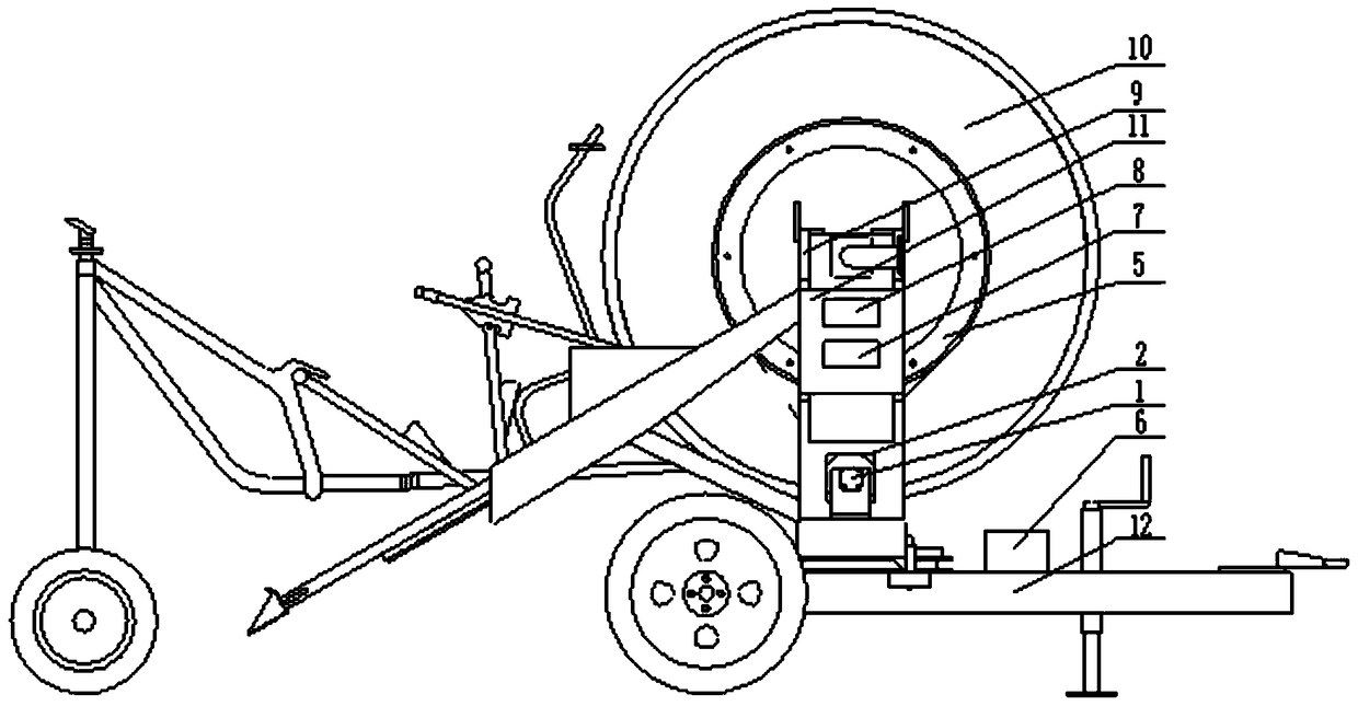
[0019] Such as figure 1 and 2 As shown, a power transmission system of a reel type sprinkler irrigation machine of the present invention, the reel type sprinkler includes a vehicle frame 12, the vehicle frame 12 is provided with a reel support 9, and the reel support 9 is provided with a reel 10. Wind the PE pipe on the reel 10, and one end of the PE pipe is connected with the nozzle car. The power transmission system includes a stepping motor 1, a reducer 2, an electromagnetic clutch 3, a small sprocket 4, a large chain ring 5, a storage battery 6, a controller 7 and a driver 8, the output of the controller 7 and the input of the driver 8 The output end of the driver 8 is connected to the input end of the stepping motor 1, the output shaft of the stepping motor 1 is connected to the input shaft of the reducer 2, and the output shaft of the reducer 2 is connected to ...


PUM


Abstract

The invention discloses a power transmission system and a working method of a reel type sprinkler irrigation machine. The output shaft of the motor is connected to the input shaft of the reducer, the output shaft of the reducer is connected to the inner hole at one end of the electromagnetic clutch, the flange at the other end of the electromagnetic clutch is connected to the small sprocket, the small sprocket is connected to the large chain ring through the chain, and the large chain ring is fixed On the reel, before the nozzle car is dragged to the work site, the electromagnetic clutch is first powered off and clutched. When the PE pipe and the nozzle car are recovered, the electromagnetic clutch is energized and closed, and the controller generates a pulse signal, which drives the stepping motor to run through the driver. The motor drives the large chain ring to rotate through the transmission structure, and the large chain ring drives the reel to rotate to recover the PE pipe and the nozzle car. The invention can precisely adjust the speed, reduce energy loss, reduce the use of mechanical structures, reduce costs, and has high reliability and high degree of automation.

Description

technical field [0001] The invention relates to the field of farmland water-saving irrigation, in particular to a power transmission system and a working method of a reel sprinkler irrigation machine suitable for farmland water-saving irrigation. Background technique [0002] With the rapid development of modern agricultural technology, the reel sprinkler has become a widely used farmland irrigation and drainage equipment. The existing reel sprinkler irrigation machine mainly uses the water pump to generate pressure water to drive the water turbine to generate power, and then drives the reel to run through the transmission device, pulls the PE pipe to wind on the winch, and pulls the sprinkler car to move and spray automatically. [0003] The water turbine currently used causes a large pressure drop, high energy consumption, and low efficiency, so a high-power water pump needs to be selected as the power source; at the same time, the existing reel sprinkler irrigation machin...

Claims


Application Information

Patent Timeline
Patent Type & Authority Patents(China)
IPC IPC(8): A01G25/09F16D27/00H02K37/24
CPCA01G25/09F16D27/00H02K37/24
Inventor 李伟魏宇吴孙阳何猛邱志鹏彭涛
Owner CHINA UNIV OF MINING & TECH
Features
  • Generate Ideas
  • Intellectual Property
  • Life Sciences
  • Materials
  • Tech Scout
  • Unparalleled Data Quality
  • Higher Quality Content
  • 60% Fewer Hallucinations
Learn More