Anti-skid rapid loading mechanism for efficient wicker splitting machine

A willow splitting machine and anti-skid technology, applied in the field of anti-skid fast feeding mechanism, can solve the problems of easy to cause large and small pieces, easy to scratch, uneven segmentation, etc., to achieve the effect of enhancing anti-skid performance

Pending Publication Date: 2020-12-11
扬中市惠丰包装有限公司
0 Cites 0 Cited by

AI-Extracted Technical Summary

Problems solved by technology

In traditional crafts, craftsmen use knives to split by hand, the splitting speed is slow, the splitting size is difficult to grasp, the splitting is uneven, and it is easy to cause large...

Abstract

The invention relates to anti-skid rapid loading mechanism for an efficient wicker splitting machine comprising a feeding cavity, a discharging cavity and a loading cavity; a feeding port of the feeding cavity is obliquely placed above a material conveying belt; a discharging plate is arranged at a discharging port of the discharging cavity; the discharging plate is erected on a second conveying shaft; the loading cavity comprises a first conveying shaft, the second conveying shaft and the material conveying belt; and a lifting device and a negative pressure device are arranged in the loadingcavity. According to the loading mechanism, wickers in the conveying process are adsorbed to the material conveying belt according to the negative pressure adsorption principle, normal loading of theloading mechanism is not affected, and meanwhile the anti-skid performance of the loading mechanism is enhanced.

Application Domain

Technology Topic

Image

  • Anti-skid rapid loading mechanism for efficient wicker splitting machine

Examples

  • Experimental program(1)

Example Embodiment

[0013]Specific implementation plan
[0014]In order to deepen the understanding of the present invention, the present invention will be described in further detail below in conjunction with embodiments and drawings. The embodiments are only used to explain the present invention and do not constitute a limitation on the protection scope of the present invention.
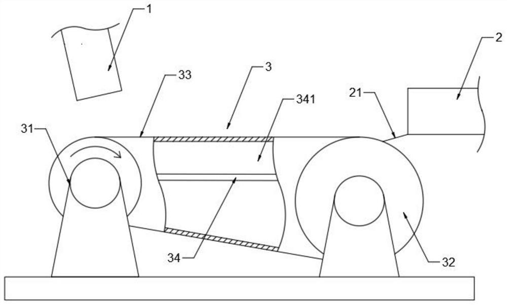
[0015]Such asfigure 1 As shown, a non-slip fast feeding mechanism for high-efficiency willow splitting machine includes a feeding cavity 1, a discharging cavity 2 and a feeding cavity 3. The feeding port of the feeding cavity 1 is placed obliquely on the material Above the conveyor belt 33, a discharge plate 21 is provided at the discharge port of the discharge chamber 2, and the discharge plate 21 is laid on the second conveying shaft 32.
[0016]Such asfigure 1 As shown, the loading chamber 3 includes a first conveying shaft 31, a second conveying shaft 32, and a material conveying belt 33. The first conveying shaft 31 and the second conveying shaft 32 are connected by the material conveying belt 33, so The loading chamber 3 is provided with a lifting device (not shown in the figure) and a negative pressure device 34. The lifting assembly includes a lifting rod and a lifting motor. The lifting device and the negative pressure device 34 are connected by a lifting rod. A negative pressure chamber 341 is formed between the negative pressure device 34 and the loading chamber 3, and a pressure sensor (not shown in the figure) is arranged in the negative pressure chamber 341, and the pressure sensor is connected to the lifting motor, The material conveyor belt 33 is provided with ventilation holes.
[0017]Working condition: When the wicker enters from the feeding chamber 1, the wicker will move with the material conveyor belt 33. At this time, the negative pressure device 34 starts to extract air from the feeding chamber 3, and the wicker is adsorbed on the material conveyor belt 33 by the negative pressure device 34 Above, because the ventilation holes on the material conveyor belt 33 are blocked by wicker, the volume of air drawn by the negative pressure device 34 per unit time remains unchanged, and the pressure in the negative pressure chamber 341 decreases. At this time, the pressure sensor (not shown) feedback The pressure signal is sent to the lifting motor (not shown in the figure), and the lifting motor controls the lifting rod to drive the negative pressure device 34 to move upward, and stop the suction work of the negative pressure device 34. At this time, the adsorption force of the wicker becomes smaller and the material passes through The conveyor belt 33 and the discharging plate 21 are transported to the discharging cavity 2 to complete the wicker feeding work.
[0018]The above descriptions are only preferred embodiments of the present invention and are not intended to limit the present invention. Any modification, equivalent replacement, improvement, etc. made within the spirit and principle of the present invention shall be included in the present invention. Within the scope of protection.

PUM

no PUM

Description & Claims & Application Information

We can also present the details of the Description, Claims and Application information to help users get a comprehensive understanding of the technical details of the patent, such as background art, summary of invention, brief description of drawings, description of embodiments, and other original content. On the other hand, users can also determine the specific scope of protection of the technology through the list of claims; as well as understand the changes in the life cycle of the technology with the presentation of the patent timeline. Login to view more.

Similar technology patents

Classification and recommendation of technical efficacy words

  • Improve skid resistance

Composite seal coat for pavement maintenance

InactiveCN102444067AImprove skid resistanceImprove performanceIn situ pavingsBituminous materialsPavement maintenance
Owner:SOUTH CHINA UNIV OF TECH

Golf glove

InactiveUS20080201822A1Improve skid resistancePrevent effectively miss hittingGlovesSport apparatusEngineeringSlip resistance
Owner:BRIDGESTONE SPORTS

Design method of reinfored rift pile for securing slope

InactiveCN1560382AImprove skid resistanceImprove local stabilityExcavationsProjected areaRift
Owner:INST OF MECHANICS - CHINESE ACAD OF SCI
Why Eureka
Try Eureka