Soft foundation reinforcing equipment for highway engineering construction

A soft foundation and engineering technology, applied in roads, roads, buildings, etc., can solve problems such as affecting physical health, dust inhalation into the lungs, breathing difficulties, etc., to ensure the service life, reduce equipment investment, and clean and beautiful surfaces.

Pending Publication Date: 2020-12-11
陕西交控产业发展集团有限公司
View PDF11 Cites 3 Cited by
  • Summary
  • Abstract
  • Description
  • Claims
  • Application Information

AI Technical Summary

Problems solved by technology

[0003] In traditional highway construction, road rollers are used to compact the road surface before construction, while traditional reinforcement works use road rollers to compact the soft ground. When performing compaction work, they generally work in sunny weather , a large amount of dust is likely

Method used


Image

  • Soft foundation reinforcing equipment for highway engineering construction
  • Soft foundation reinforcing equipment for highway engineering construction
  • Soft foundation reinforcing equipment for highway engineering construction

Examples


Embodiment 1

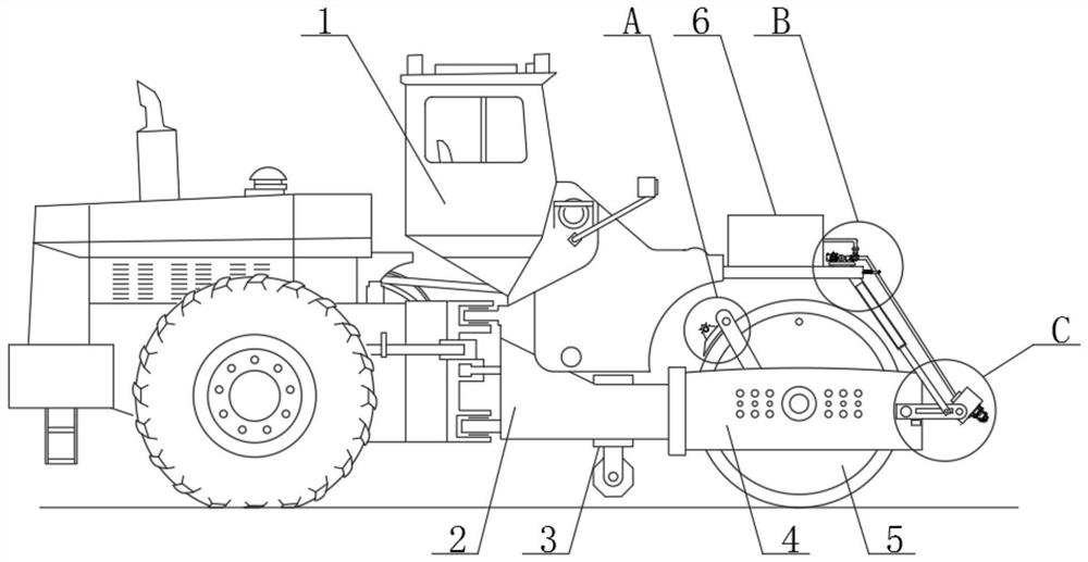
[0025] see figure 1 , figure 2 , image 3 , Figure 4 , Figure 5 and Figure 6 , the present invention provides a technical solution:

[0026]A soft ground reinforcement equipment for highway engineering construction, comprising a road roller 1 and a connecting body 2, the connecting body 2 is fixedly connected under the road roller 1, and a rapping mechanism 3 is fixedly connected inside the connecting body 2, and the rapping mechanism 3 includes a fixed frame 301 and The sliding plate 302, the outside of the fixed frame 301 is fixedly connected with the connecting body 2, the inside of the fixed frame 301 is slidably connected with the sliding plate 302, the upper end surface of the sliding plate 302 is fixedly connected with the sliding rod 303, and the lower end surface of the sliding plate 302 is fixedly connected with the front and back distribution. The fixed plate 309 and the rapping roller 310 are arranged under the sliding plate 302. The front and rear end sur...

Embodiment 2

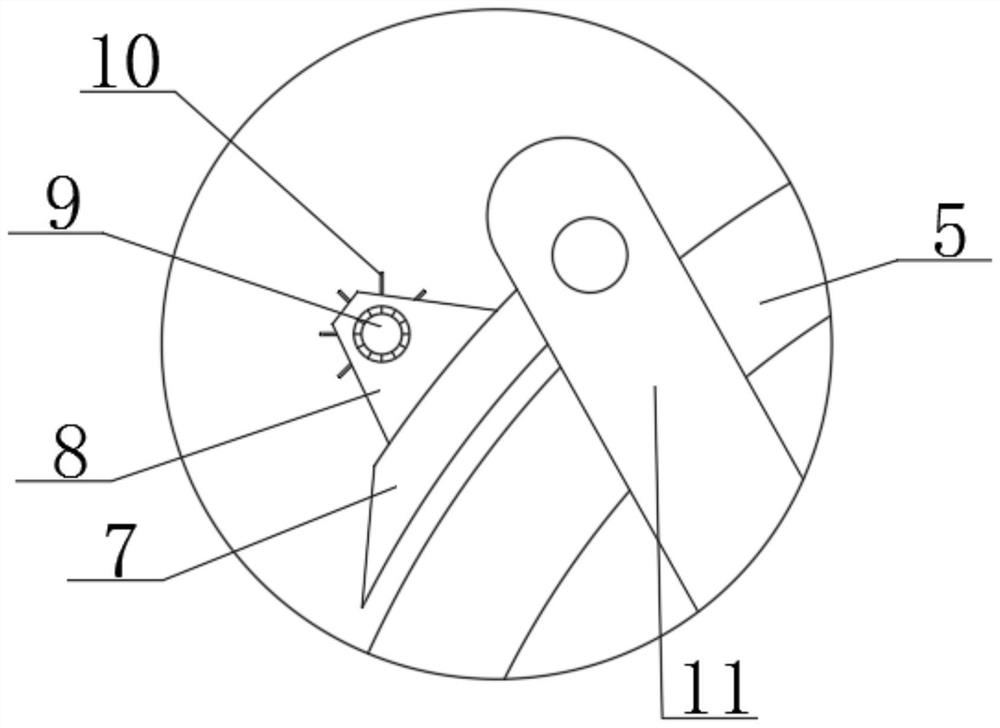
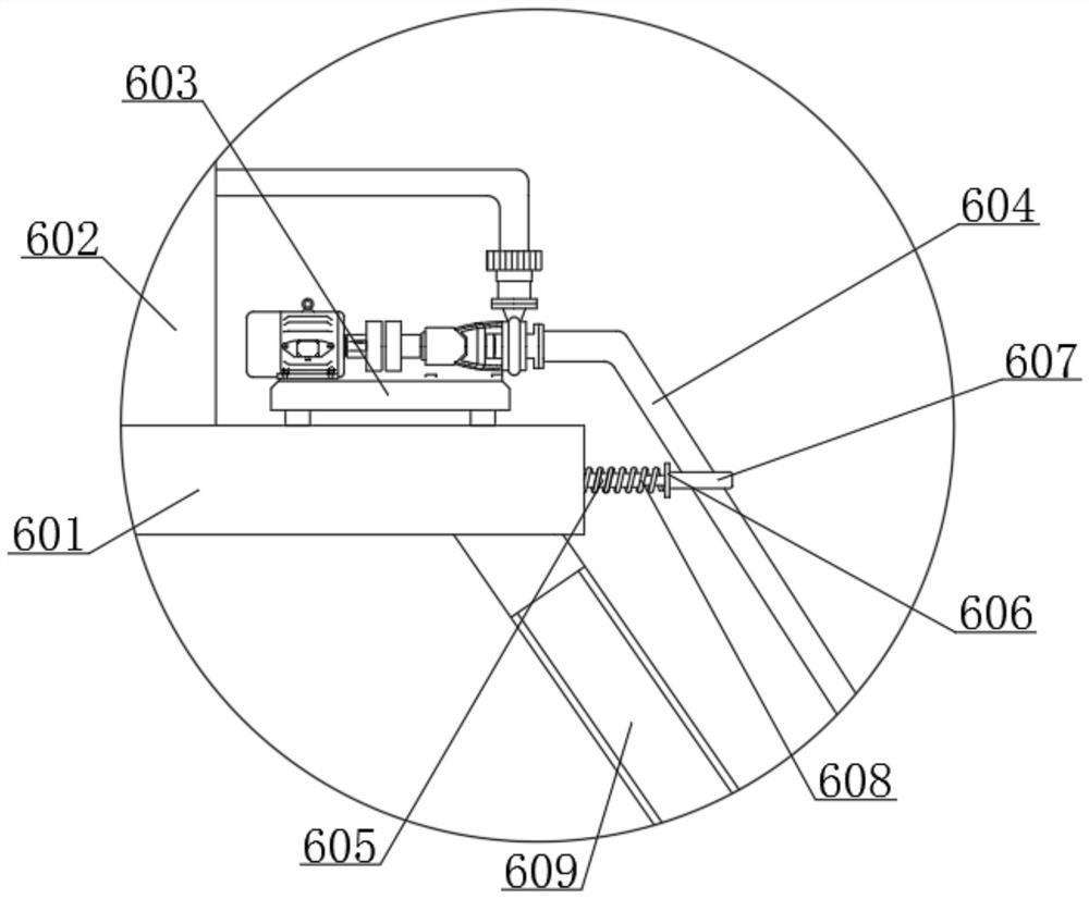
[0029] In Embodiment 2, the same parts as in Embodiment 1 will not be repeated. The difference is that when the device is not in use, the sliding block 610 can be driven to slide on the outside of the rotating plate 611 by starting the electric telescopic rod 609 at this time, thereby turning the rotating plate 611 drives the upward rotation, and then drives the hollow tube 614 upward rotation to make it vertically placed, saving space. At this time, under the action of the telescopic spring 608, it pushes the fixed block 606 to move to the right, and the telescopic rod 605 is in a stretched state, ensuring The water pipe 604 moves to the right to make it stretched, avoiding its entanglement, avoiding its contact with the roller 5, and ensuring the normal use of the water pipe 604, and the set stopper 613 can play the purpose of supporting the rotating plate 611.


PUM


Abstract

The invention relates to the technical field of highway construction, in particular to soft foundation reinforcing equipment for highway engineering construction. The soft foundation reinforcing equipment comprises a road rolling machine and a connecting body, the lower part of the road rolling machine is fixedly connected with the connecting body, a rapping mechanism is fixedly connected into theconnecting body, and a pushing frame is fixedly connected to the right end surface of the connecting body; and a road roller is rotatably connected into the pushing frame, connecting columns distributed in the front-back direction are fixedly connected to the upper end face of the pushing frame, scrapers are fixedly connected to the inner sides of the connecting columns, and fixing tables distributed in the front-back direction are fixedly connected to the upper end faces of the scrapers. According to the soft foundation reinforcing equipment, through arrangement of a containing plate water pump, a hollow pipe and an atomizing spray head, when the equipment is started, dust falling work can be conducted in advance through the atomizing spray head, it is guaranteed that no dust is raised when the equipment works, at the moment, workers are not prone to inhaling the dust, and the life safety of the workers is guaranteed.

Description

technical field [0001] The invention relates to the technical field of road construction, in particular to a soft ground reinforcement device for road engineering construction. Background technique [0002] The road roller, also known as the soil compactor, is a kind of equipment for road construction. The road roller belongs to the category of road equipment in construction machinery. For practical operation, it can roll sandy, semi-cohesive and cohesive soil, roadbed stabilized soil and asphalt concrete pavement layer. The road roller is suitable for various compaction operations due to the gravity of the machine itself, so that the rolled layer will produce permanent deformation and compactness. , The road roller is divided into two types: steel wheel type and tire type. [0003] In traditional highway construction, road rollers are used to compact the road surface before construction, while traditional reinforcement works use road rollers to compact the soft ground. Whe...

Claims


Application Information

Patent Timeline
IPC IPC(8): E01C19/26E01C3/04B01D47/06
CPCE01C19/26E01C3/04B01D47/06
Inventor 付宏伟王宇张佳尹亮
Owner 陕西交控产业发展集团有限公司
Why Eureka
Try Eureka