Pedal arm welding strength detection device and method
A welding strength and detection device technology, which is applied in the direction of measuring devices, strength characteristics, and mechanical devices, can solve the problems of low automation, simple functions, and low accuracy of detection results, and achieve a high degree of automation and high accuracy of detection results. Effect
- Summary
- Abstract
- Description
- Claims
- Application Information
AI Technical Summary
Problems solved by technology
Method used
Image

Examples
Embodiment Construction
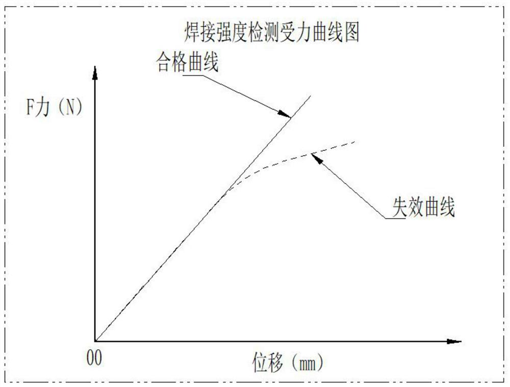
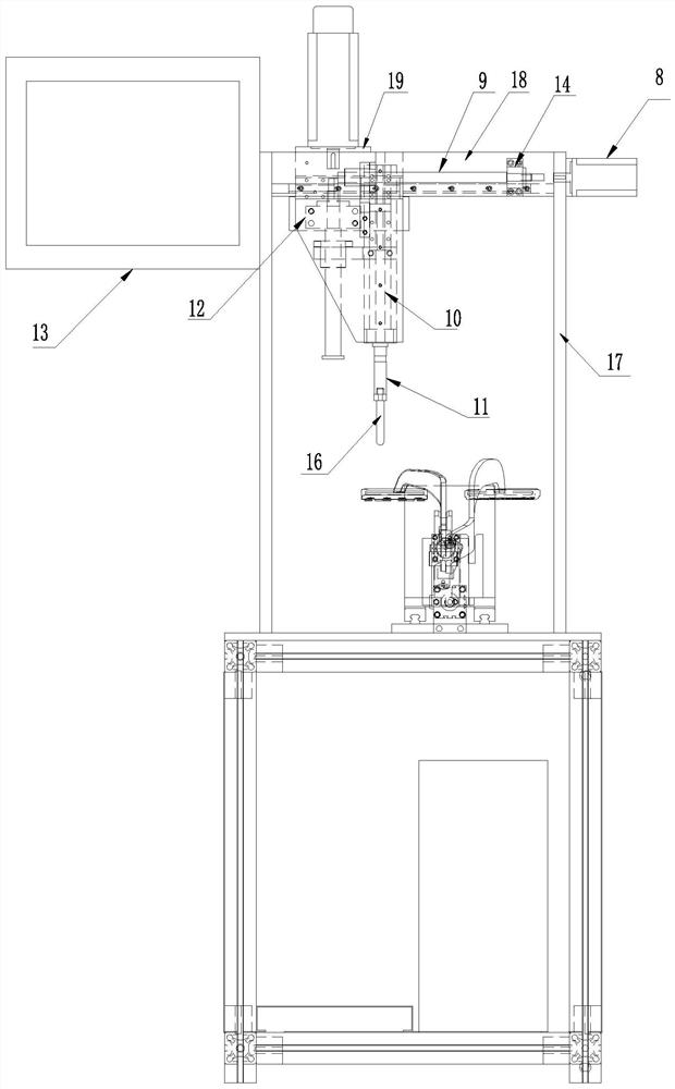
[0036] see Figure 2-Figure 5 , a pedal arm welding strength detection device, including a workbench, the workbench is provided with a clamp body 5 for installing the pedal arm 2, the workbench is provided with a detection frame, and the detection frame is provided with a drive system, the drive system is connected to the measuring head 16 through the S-shaped force sensor 11, and the measuring head is used to apply force to the pedal body at the end of the pedal arm to detect the welding strength of the welding spot at the joint between the pedal arm and the pedal body. The system is used to drive the measuring head to translate and move vertically.
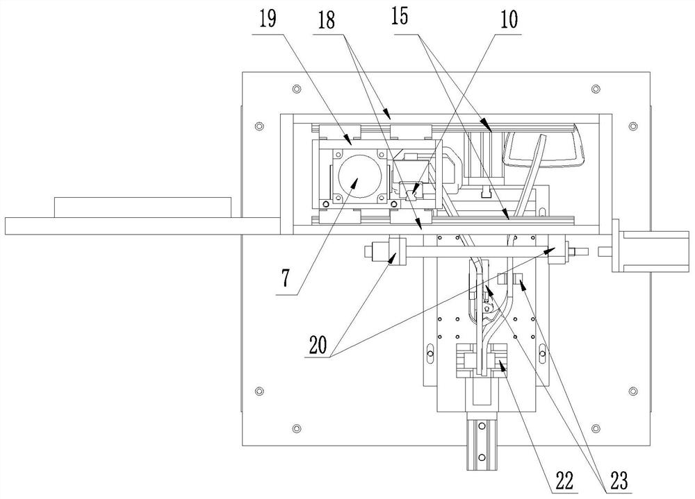
[0037] Described detection rack comprises the vertical plate 17 of two parallel arrangements, and two vertical plates are positioned at the both sides of clip body 5, is connected with two horizontal plates 18 that are arranged in parallel between the top of described two vertical plates, is provided with between two horizontal ...
PUM
 Abstract
Description
Claims
Application Information
 - Generate Ideas
- Intellectual Property
- Life Sciences
- Materials
- Tech Scout
- Unparalleled Data Quality
- Higher Quality Content
- 60% Fewer Hallucinations
Browse by: Latest US Patents, China's latest patents, Technical Efficacy Thesaurus, Application Domain, Technology Topic, Popular Technical Reports.
© 2025 PatSnap. All rights reserved.Legal|Privacy policy|Modern Slavery Act Transparency Statement|Sitemap|About US| Contact US: help@patsnap.com