
Optical axis parallelism correction method for multi-detector system based on laser displacement sensor

A technology of laser displacement and correction method, which is applied in the direction of instruments, optics, measuring devices, etc., can solve the problems of increasing system structural stress, the adjustment amount cannot be quantified, and the workload is large, so as to improve the correction accuracy and improve the optical axis parallelism correction Efficiency and the effect of reducing the difficulty of operation

Active Publication Date: 2022-06-17
西安应用光学研究所
View PDF9 Cites 0 Cited by
  • Summary
  • Abstract
  • Description
  • Claims
  • Application Information

AI Technical Summary

Problems solved by technology

However, during the adjustment process, only one of the azimuth or pitch angles can be adjusted using shims, and the other angle can only be adjusted through the oblong holes reserved in the structure; the adjustment amount cannot be quantified during the adjustment process of the oblong holes, and only rely on manual experience through repeated disassembly and assembly It takes a long time and a lot of work to adjust, and multiple disassembly and assembly can easily increase the structural stress of the system

Method used


Image

  • Optical axis parallelism correction method for multi-detector system based on laser displacement sensor
  • Optical axis parallelism correction method for multi-detector system based on laser displacement sensor
  • Optical axis parallelism correction method for multi-detector system based on laser displacement sensor

Examples


Embodiment Construction

[0034] In order to make the purpose, content and advantages of the present invention clearer, the specific embodiments of the present invention will be described in further detail below with reference to the accompanying drawings and embodiments.

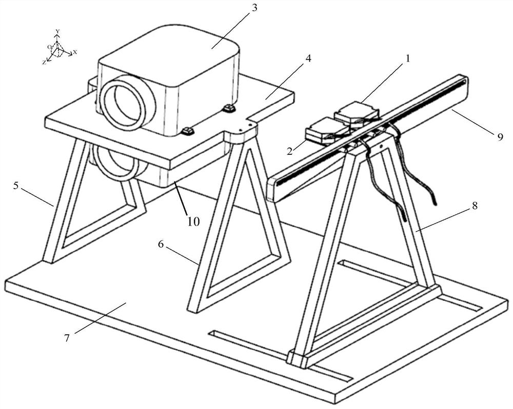
[0035] First, the present invention provides a multi-detector system optical axis parallelism correction system based on a laser displacement sensor, refer to image 3 As shown, the correction system includes:

[0036] Optical axis correction platform 7;

[0037] The optical bench 4 is installed on the optical axis correction platform 7, on which the photodetector 3 to be corrected and the reference photodetector 10 are installed; The bench fixing bracket two 6, the optical bench 4 is installed on the optical bench fixing bracket 1 5 and the optical bench fixing bracket 2 6, so as to be supported and fixed; the photodetector 3 to be calibrated is installed above the optical bench 4, and the reference The photodetector 10 is instal...


PUM


Abstract

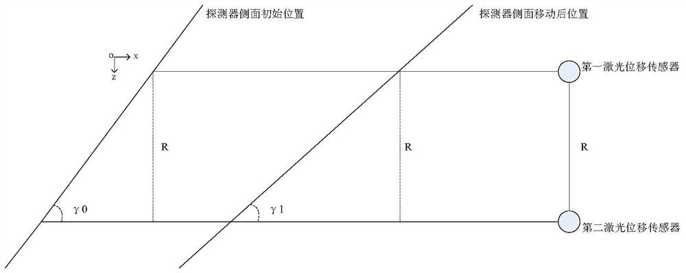
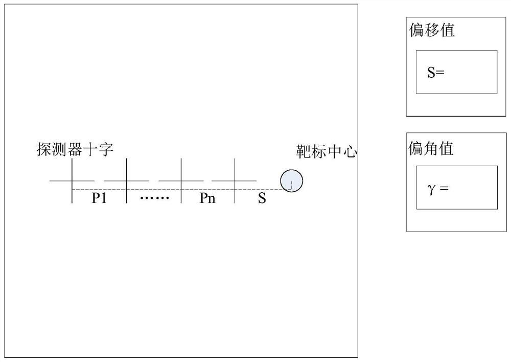
The invention discloses a method for correcting the optical axis parallelism of a multi-detector system based on a laser displacement sensor. First, using the angle measurement principle of a double laser displacement sensor to measure the deflection angle of the side plane of the corrected detector; Adjust the deflection angle on the plane and the offset of the cross center in the detector output image, and establish a mathematical model between the two; 3. Obtain the deviation between the cross center and the target in the detector output image through the image processing algorithm, and bring it to the detector side The adjustment amount of the detector side plane angle is obtained in the mathematical model of the plane adjustment deflection angle and the offset of the image cross center; 4. Adjust the amount of the oblong hole so that the digital display value of the angle measurement system of the dual laser displacement sensor and the obtained deflection angle adjustment amount If they are consistent, the parallelism correction of the optical axis of the detector is completed. The method of the invention quantifies the adjustment amount of the oblong hole in the optical axis correction, the correction process is visualized and easy to operate, the correction accuracy is high, and the deflection angle adjustment amount can be recorded, and it is used for subsequent disassembly and reassembly without recalibration.

Description

technical field [0001] The invention belongs to the technical field of optical axis adjustment of a multi-detector platform photoelectric system, and relates to a method for correcting the optical axis parallelism of a multi-detector system based on a laser displacement sensor. Background technique [0002] In order to meet the needs of all-weather, intelligent and complex use environments of optoelectronic equipment, a multi-mode platform optoelectronic system composed of multiple optoelectronic sensors has been developed and put into use. In the development and production process of the multi-sensor platform photoelectric system, the parallelism of the optical axis of each sensor needs to be corrected many times to ensure the indication accuracy of the photoelectric device. [0003] At present, the commonly used optical axis parallelism correction method is to adjust the azimuth or pitch angle of the detector through the observation of the target in the collimator by the d...

Claims


Application Information

Patent Timeline
Patent Type & Authority Patents(China)
IPC IPC(8): G02B27/30G01B11/26
CPCG02B27/30G01B11/26
Inventor 孙浩周晓斌文江华刘召庆原琦张衡吴妍金明鑫吴奉泽
Owner 西安应用光学研究所
Learn More