Equipment host

A device host and host technology, applied to electrical components, electrical switches, circuits, etc., can solve problems such as easy water ingress, short service life of keys, poor sealing and waterproof performance, etc., to increase the sealing and waterproof, The effect of increasing the service life and increasing the heat dissipation

Inactive Publication Date: 2020-12-11
蒋程科
View PDF0 Cites 1 Cited by
  • Summary
  • Abstract
  • Description
  • Claims
  • Application Information

AI Technical Summary

Problems solved by technology

[0002] In the prior art, the equipment generally has a host case, such as a computer, server, etc. When in use, the host case will generate a large amount of heat when in use, so a cooling device is generally provided, so the case is provided with an air intake However, in order to prevent external dust from being sucked in, the suction port is generally set very small to filter dust and prevent dust from entering the inside of the chassis, but this method causes the chassis to have multiple air inlets and outlets, sealing and The water resistance is poor. These air intake filter holes are always in a conduction state when the host is not in use, and are easily affected by the external environment. Frequent cleaning, the traditional method is very inconvenient due to the integrated structure of the filter and the host, so it is difficult to disassemble and clean
[0003] In addition, the main engine chassis is generally in the form of external buttons, that is, the buttons are set outside, so that it is convenient to operate the switch, which also makes the switch buttons easy to be damaged, and it is also easy to enter water, resulting in damage to the buttons and a short service life of the buttons.

Method used


Image

  • Equipment host
  • Equipment host
  • Equipment host

Examples


Embodiment Construction

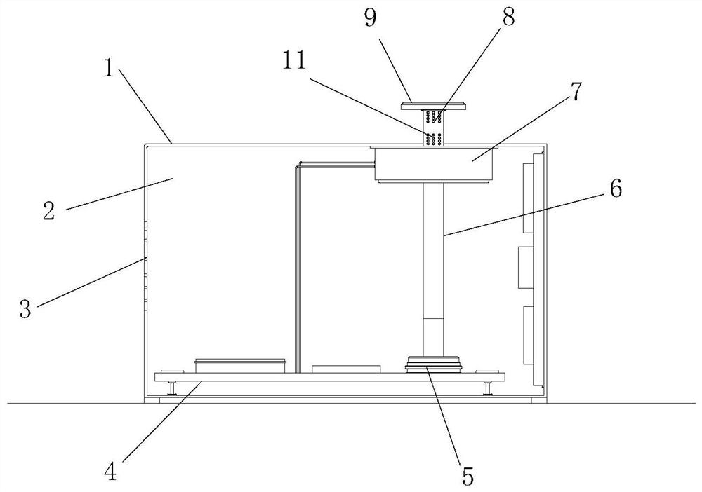
[0021] like figure 1 As shown, the host of the device includes a host box 1, an installation cavity 2 is arranged inside the host box 1, a host motherboard 4 is installed on the bottom surface of the installation cavity 2, and a power-on button 5 is arranged on the host motherboard 4. In this embodiment , The power-on button 5 adopts a mechanical self-locking button switch. This switch button is relatively common. Press once to drop, and press again to bounce.

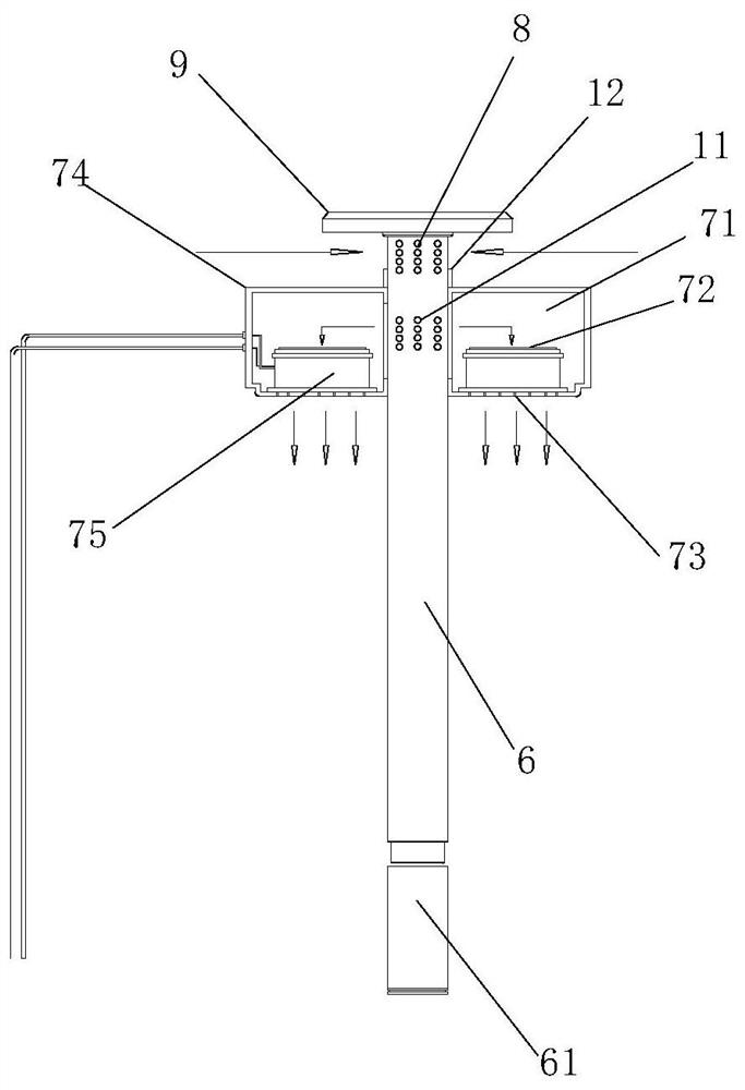
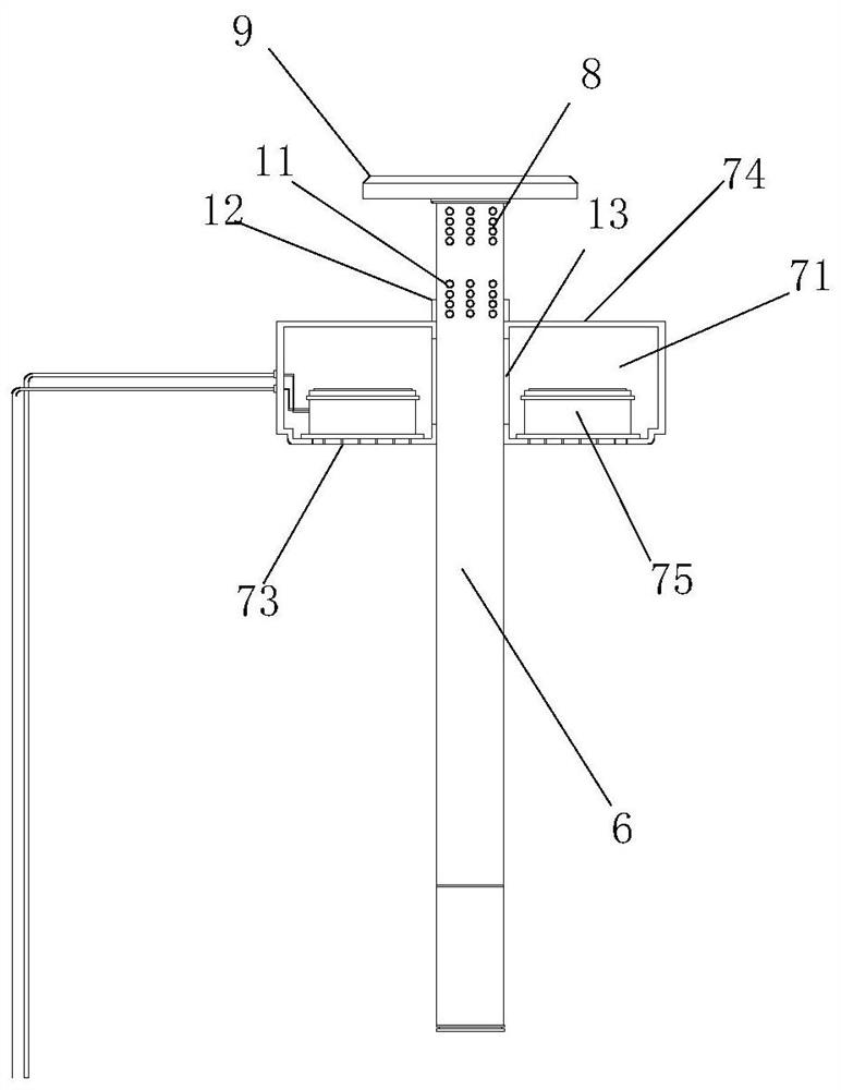
[0022] A heat sink 7 is fixedly installed on the top surface of the installation cavity 2 of the main engine case 1, and a first through hole is formed through the heat sink 7 from top to bottom, and a second through hole is arranged on the main engine case facing the first through hole. , set a filter rod through the first and second through holes, the bottom of the filter rod is in contact with the top of the power-on button, and part of the filter rod protrudes from the top outer side of the main box. When the power...


PUM


Abstract

The invention discloses an equipment host. The host comprises a host box body, a mounting cavity is formed in the host box body, a host mainboard is mounted on the bottom surface of the mounting cavity, a power-on key is arranged on the host mainboard, a mechanical self-locking button switch is adopted as the power-on key, and a heat dissipation device is fixedly mounted on the top surface of themounting cavity of the host box body. A first through hole is formed in the heat dissipation device from top to bottom in a penetrating mode, a second through hole is formed in the mainframe box bodyright opposite to the first through hole, a filtering rod penetrates through the first through hole and the second through hole, the bottom of the filtering rod makes contact with the top of the power-on key, and the filtering rod partially stretches out of the outer side face of the top of the mainframe box body. According to the equipment host, a traditional startup and shutdown key is hidden, an air inlet filter screen is omitted, the sealing performance and the waterproofness of the host box body are improved, the dust removal effect is improved, and filter screen holes are prevented frombeing blocked.

Description

technical field [0001] The invention relates to the field of electronic equipment, in particular to a device host. Background technique [0002] In the prior art, the equipment generally has a host case, such as a computer, server, etc. When in use, the host case will generate a large amount of heat when in use, so a cooling device is generally provided, so the case is provided with an air intake However, in order to prevent external dust from being sucked in, the suction port is generally set very small to filter dust and prevent dust from entering the inside of the chassis, but this method causes the chassis to have multiple air inlets and outlets, sealing and The water resistance is poor. These air intake filter holes are always in a conducting state when the host is not in use, and are easily affected by the external environment on the interior of the host. Dust is filtered at the position of the air intake holes, so it is often blocked, so it needs Frequent cleaning, t...

Claims


Application Information

Patent Timeline
Patent Type & Authority Applications(China)
IPC IPC(8): H01H9/04H01H9/52H01H13/02H01H13/14
CPCH01H9/04H01H9/52H01H13/02H01H13/14
Inventor 蒋程科
Owner 蒋程科
Why Eureka
Try Eureka