Crimping tool

A tooling and terminal technology, applied in the field of crimping tooling, can solve the problems that the wire and the terminal cannot be physically connected closely, the curvature cannot be changed, and the wire cannot be tightly wrapped.

Active Publication Date: 2020-12-11
廊坊市永旺汽车部件有限公司
View PDF6 Cites 0 Cited by
  • Summary
  • Abstract
  • Description
  • Claims
  • Application Information

AI Technical Summary

Problems solved by technology

[0005] Since the arc-shaped guide surface is determined and unchangeable, the curvature of the side plate cannot be changed after being crimped. If the radial size o

Method used


Image

  • Crimping tool
  • Crimping tool
  • Crimping tool

Examples


Embodiment Construction

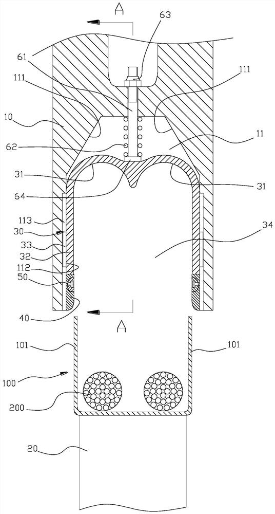
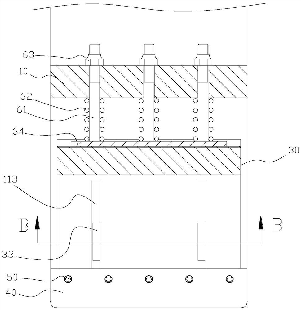
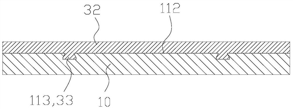
[0039] Unless otherwise defined, the technical terms or scientific terms used in the present invention shall have the usual meanings understood by those skilled in the art to which the present invention belongs. "First", "second" and similar words used in the present invention do not indicate any order, quantity or importance, but are only used to distinguish different components. "Comprising" or "comprising" and similar words mean that the elements or items appearing before the word include the elements or items listed after the word and their equivalents, without excluding other elements or items. Words such as "connected" or "connected" are not limited to physical or mechanical connections, but may include electrical connections, whether direct or indirect. "Up", "Down", "Left", "Right" and so on are only used to indicate the relative positional relationship. When the absolute position of the described object changes, the relative positional relationship may also change acc...


PUM


Abstract

The invention discloses a crimping tool. The tool comprises: a pedestal, wherein the upper end of the pedestal forms a flat storage surface which is used for the storage of a wiring terminal; an upperdie located above the pedestal, wherein the upper die is provided with a guide cavity with a downward opening, and the bottom of the guide cavity is provided with two guide inclined planes which arearranged at an angle; and a movable die formed by an elastic metal material, wherein the movable die is arranged in the guide cavity, the movable die is provided with a die cavity facing the pedestal,and two parallel arc-shaped guide surfaces are formed at the bottom of the die cavity. When the movable die slides into the two guide inclined planes, the guide inclined planes force the curvatures of the two arc-shaped guide surfaces at the bottom of the die cavity to be increased.

Description

technical field [0001] The invention relates to a crimping tool for connecting wires to terminal blocks. Background technique [0002] In the prior art, there is a crimping tool, which includes a base and an upper mold arranged above the base, and the upper mold has a cavity with the opening facing downward, and the cavity bottom of the cavity has two parallel arcs Shaped guide surface. [0003] The working principle of the above-mentioned crimping tool is: place the terminal with a U-shaped cross section on the base, and then place the two wires to be connected side by side on the bottom of the terminal; use hydraulic or air pressure to drive the upper die downward Move to make the two side plates of the terminal slide into the mold cavity. When the side plates reach the bottom of the mold cavity, the two arc-shaped guide surfaces respectively force the two side plates to curl and cover the two wires respectively, and then Realize the crimping of terminal blocks and wires...

Claims


Application Information

Patent Timeline
IPC IPC(8): H01R43/058
CPCH01R43/058
Inventor 李永健郭春清张元浩
Owner 廊坊市永旺汽车部件有限公司
Why Eureka
Try Eureka