Steel bar clamping device

A clamping device and steel bar technology, which is applied in the field of steel bar clamping devices, can solve the problems of steel bar rotation, affecting the machining accuracy of steel bar threads, and insufficient clamping force, etc.

Pending Publication Date: 2022-01-25
大同市建航机械制造有限公司
View PDF1 Cites 0 Cited by
  • Summary
  • Abstract
  • Description
  • Claims
  • Application Information

AI Technical Summary

Problems solved by technology

[0002] The existing steel bar clamping device used for steel bar thread processing equipment usually uses a screw to drive the two jaws to move and clamp the steel bar. "Clamping mechanism" invention patent, but due to the limited space of the screw structure, the clamping force is not enough, which often leads to the rotation of the steel bar during processing, which affects the machining accuracy of the steel bar thread.

Method used


Image

  • Steel bar clamping device
  • Steel bar clamping device
  • Steel bar clamping device

Examples


Embodiment Construction

[0024] In order to make the technical problems, technical solutions and beneficial effects to be solved by the present invention clearer, the present invention will be further described in detail in combination with the embodiments and accompanying drawings. It should be understood that the specific embodiments described here are only used to explain the present invention, not to limit the present invention. The technical solutions of the present invention will be described in detail below in conjunction with the embodiments and accompanying drawings, but the scope of protection is not limited thereto.

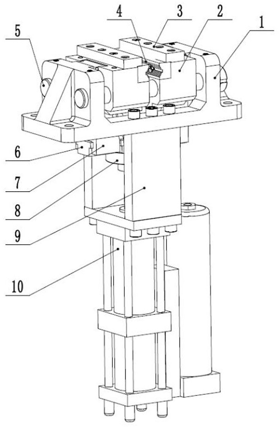
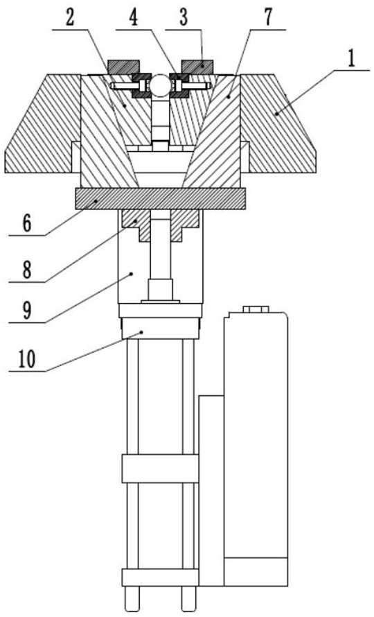
[0025] Such as figure 1 As shown in -5, the present invention provides a steel bar clamping device, including a base 1, a jaw body 2, an inclined block 7, a top plate 6, a support sleeve 8, a fixed bracket 9, and a gas-liquid booster cylinder 10.

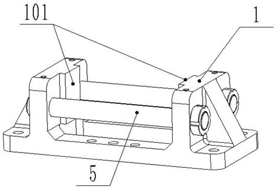
[0026] The base 1 includes a bottom plate and two side plates, the bottom plate is a square plate structure arranged horizontally...


PUM


Abstract

The invention relates to a steel bar clamping device, and belongs to the technical field of building mechanical equipment. The device comprises a base, jaw bodies and a top plate, and a vertically-through mounting hole is formed in the center of the base; and two inclined blocks are symmetrically arranged at the two ends of the upper end face of the top plate and inserted into the mounting hole, and sliding strips are symmetrically arranged at the edges, close to each other, of the two sides of each inclined block correspondingly to form a V-shaped structure. The two jaw bodies are symmetrically arranged between the two inclined blocks, inclined grooves are formed at the ends, away from each other, of the jaw bodies, the inclined blocks are sleeved with the jaw bodies through the inclined grooves, sliding grooves are formed at the two sides of each inclined groove, sliding strips are connected into the sliding grooves in a sliding manner, jaws are arranged on the end faces, close to each other, of the jaw bodies, and a horizontal polished rod is arranged at the upper end of the base. The two jaw bodies sleeve the polished rod; and the lower end of the top plate is connected with a piston rod of a gas-liquid pressure cylinder which is connected with the base through a fixing support. The problem that an existing steel bar clamping device adopting a lead screw structure is insufficient in clamping force is solved.

Description

technical field [0001] The invention belongs to the technical field of construction machinery and equipment, and in particular relates to a steel bar clamping device. Background technique [0002] The existing steel bar clamping device used for steel bar thread processing equipment usually uses a screw to drive the two jaws to move and clamp the steel bar. However, due to the limited structural space of the lead screw, the clamping force is not enough, which often leads to the rotation of the steel bar during processing, which affects the machining accuracy of the steel bar thread. Contents of the invention [0003] The invention overcomes the deficiencies of the prior art, and proposes a steel bar clamping device; it solves the problem of insufficient clamping force of the steel bar clamping device currently adopting a screw structure. [0004] In order to achieve the above object, the present invention is achieved through the following technical solutions. [0005] The...

Claims


Application Information

Patent Timeline
Patent Type & Authority Applications(China)
IPC IPC(8): B21H3/02
CPCB21H3/02
Inventor 徐晓桐
Owner 大同市建航机械制造有限公司
Why Eureka
Try Eureka