
Iron core lamination manufacturing method

A manufacturing method and core lamination technology, which are applied in the field of core lamination manufacturing, can solve the problems of difficult to precisely control the thickness of the adhesive layer, easy wire breakage, broken pieces, etc., so as to avoid designing and processing high-precision lamination tooling, eliminating the iron core Effects requiring low vibration noise, strength and toughness

Active Publication Date: 2020-12-11
上海和兰透平动力技术有限公司
View PDF4 Cites 0 Cited by
  • Summary
  • Abstract
  • Description
  • Claims
  • Application Information

AI Technical Summary

Problems solved by technology

Manual gluing has low labor productivity, and the thickness of the glue layer is difficult to accurately control; machine gluing requires a large investment, which is not suitable for small-scale production, and has certain requirements for the strength of loose pieces, which can easily cause broken pieces, and is not suitable for small and micro Manufacture of the iron core; the brushing method usually uses the method of first bonding the blanks into stacks and then wire-cutting the iron core. Due to the poor conductivity of the adhesive layer, wire cutting is difficult, time-consuming and easy to break, which greatly reduces labor productivity.

Method used


Image

  • Iron core lamination manufacturing method
  • Iron core lamination manufacturing method
  • Iron core lamination manufacturing method

Examples


Embodiment 1

[0055] The manufacturing method of iron core lamination comprises the following steps:

[0056] The method for manufacturing iron core laminations is characterized in that it comprises the following steps:

[0057] 1. Align and stack the loose cores of the same type into a stack of loose cores;

[0058] 2. Connect and fix the peripheral part of the iron core loose piece stack that exceeds the margin of the finished iron core, without affecting the quality of the finished iron core;

[0059] 3. Use the cutting method to process the inner hole of the iron core;

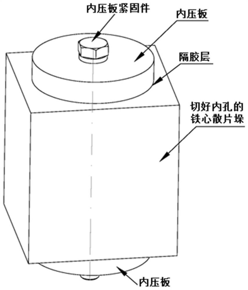
[0060] Four. If figure 1 As shown, the upper and lower inner pressure plates are respectively placed on the upper and lower ends of the core loose piece stack, and the inner pressure plate fasteners are used to press the upper and lower inner pressure plates on the upper and lower ends of the iron core loose piece stack to fix them with the iron core loose piece stack. The radial dimension of the upper inner pressure...

Embodiment 2

[0074] Based on the manufacturing method of core laminations in implementation 1, in step 4, the top and bottom of the stack of loose cores are coated or stacked with insulating materials, such as silicone grease coating, or stacked release paper, etc., to facilitate later dipping After curing and forming, it will be separated from the tooling.

[0075] Preferably, in step 1, the core loose pieces have no holes or slots passing through from top to bottom.

[0076] Preferably, in step 1, according to the weight of the loose iron core pieces of the model, the required amount of loose iron core pieces is weighed according to the stacking coefficient.

[0077] Preferably, in step 2, the peripheral part of the stack of loose pieces of the iron core that exceeds the margin of the shaped iron core is connected and fixed by means of welding, bonding, riveting or buckling.

[0078] Preferably, in step 3, cutting methods such as wire cutting and laser cutting are used to complete the i...

Embodiment 3

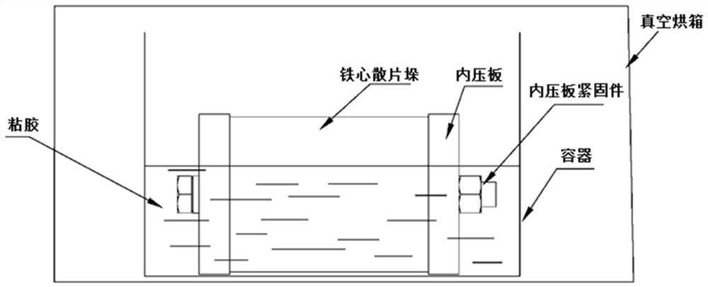
[0084] Based on the manufacturing method of core laminations in implementation 1, in step 6, the viscose surface is immersed in the axis of the lamination stack, and a part of the lamination stack is exposed above the viscose surface.

[0085] Preferably, in step 6, pretreatment (for example, drying, preheating, etc.) before dipping is performed on the stack of scattered iron cores fixed by the inner pressure plate, and then the stack of scattered iron cores fixed by the inner pressure plate is placed horizontally in the container In the viscose.

[0086] Preferably, in step 6, before placing the container into the oven and placing the stack of loose iron cores fixed by the inner pressure plate horizontally in the glue in the container, preheat the vacuum oven, and the preheating temperature is lower than that of the glue curing temperature.


PUM


Abstract

The invention discloses an iron core lamination manufacturing method, which comprises the following steps of: stacking iron core scattered sheets of the same model into an iron core scattered sheet stack, connecting and fixing the allowance part of the iron core scattered sheet stack exceeding a finished iron core, and cutting the iron core scattered sheet stack into an iron core middle shape by utilizing linear cutting, laser cutting or other processing modes, then, additionally arranging an inner pressing plate to press the iron core scattered sheet stack, then, cutting the iron core appearance, ensuring the iron core size and position precision through the cutting machining precision, then, performing vacuum impregnation on the iron core scattered sheet stack through the capillarity phenomenon, and then performing heating curing. According to the iron core lamination manufacturing method, a used tool is only a pressing plate with good parallelism and uses a common fastener, the requirement for tool precision is low, the problems that in a traditional lamination mode, silicon steel sheet crystals are broken, an insulating layer is locally damaged, and loss heating is high can besolved, iron core scattered sheet gaps can be fully filled, iron core heat conduction is enhanced, and the iron core fanning phenomenon and the iron core vibration noise can be eliminated.

Description

technical field [0001] The invention relates to an iron core manufacturing process, in particular to an iron core lamination manufacturing method. Background technique [0002] Iron core is an important part of transformers and motors. When the motor is working, the iron core has to bear the combined effects of mechanical vibration, electromagnetic force and heat. [0003] The iron core of the motor is generally punched, and the iron core lamination means that a certain number of punched sheets are aligned, pressed, and fixed into an accurate, compact and suitable whole. Generally, circular iron cores use tire-expanding core laminations and press-fitting tools to tighten the iron core to make the inner circle neat, and then press the iron core on the press machine. Rectangular or other shaped iron cores also adopt similar principles. bit tooling for lamination. [0004] Punching is suitable for thicker (≥0.15mm) core pieces. The mold is expensive to make, and the punching...

Claims


Application Information

Patent Timeline
IPC IPC(8): H02K15/02H02K15/12
CPCH02K15/02H02K15/12
Inventor 郑甜华高闯邢冬燕张成王胜
Owner 上海和兰透平动力技术有限公司
Learn More