Automatic checkered steel plate machining device with anti-skid and warning functions
A patterned steel plate, automatic processing technology, applied to the surface coating liquid device, coating, etc., can solve the problem of high working strength of artificial bonding friction materials, high anti-skid performance requirements of patterned steel plate, difficulty in meeting safety requirements, etc. problems, to avoid accidents, increase the coefficient of friction, and reduce waste
- Summary
- Abstract
- Description
- Claims
- Application Information
AI Technical Summary
Problems solved by technology
Method used
Image

Examples
Embodiment Construction
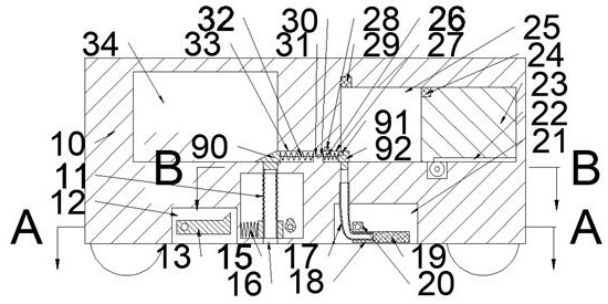
[0017] Combine below Figure 1-4 The present invention is described in detail, wherein, for the convenience of description, the orientations mentioned below are defined as follows: figure 1 The up, down, left, right, front and back directions of the projection relationship itself are the same.
[0018] An automatic processing device for checkered steel plates with anti-skid and warning functions described in conjunction with accompanying drawings 1-4, includes a main box body 10, and an adhesive cavity 25 is provided inside the main box body 10, and the adhesive agent The lower side of the chamber 25 is communicated with a right channel 62, and the lower side of the right channel 62 is communicated with a brush chamber 21 with an opening downward. The rear side of the brush chamber 21 is provided with a linkage belt chamber 35 extending to the left. The rear side of the linkage belt chamber 35 is provided with a wire wheel chamber 39, and the right side of the wire wheel cham...
PUM
 Abstract
Description
Claims
Application Information
 - R&D
- Intellectual Property
- Life Sciences
- Materials
- Tech Scout
- Unparalleled Data Quality
- Higher Quality Content
- 60% Fewer Hallucinations
Browse by: Latest US Patents, China's latest patents, Technical Efficacy Thesaurus, Application Domain, Technology Topic, Popular Technical Reports.
© 2025 PatSnap. All rights reserved.Legal|Privacy policy|Modern Slavery Act Transparency Statement|Sitemap|About US| Contact US: help@patsnap.com