

Onion slitting device
Patent Information
- Authority / Receiving Office
- CN · China
- Patent Type
- Applications(China)
- Current Assignee / Owner
- 李美霞
- Publication Date
- 2020-12-15
- Estimated Expiration
- Not applicable · inactive patent
Smart Images
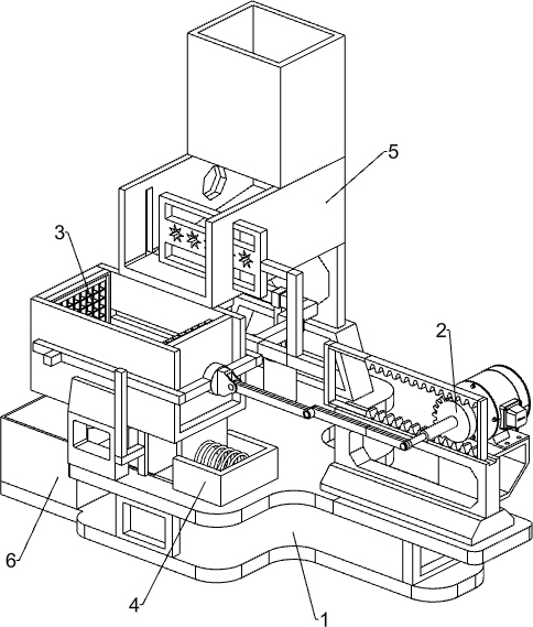
Figure 1 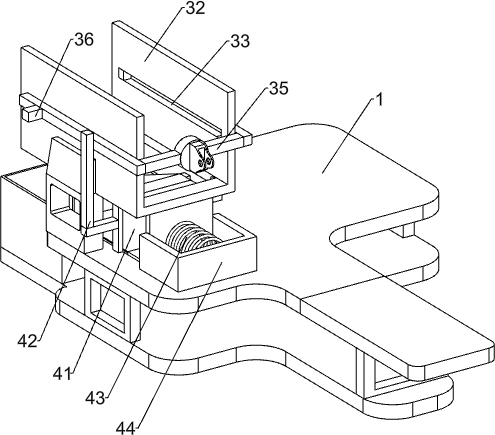
Figure 2 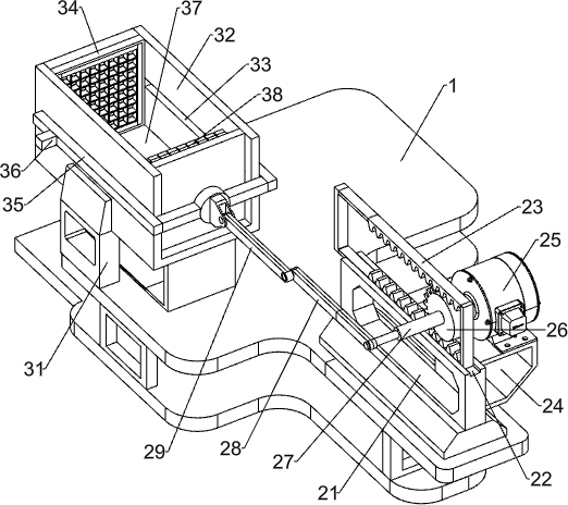
Figure 3
Abstract
Description
technical field
[0001] The invention relates to a strip cutting device, in particular to an onion strip cutting device. Background technique
[0002] Onions are a very common household dish. Its meat is tender, juicy, spicy and light, and of good quality, suitable for raw food. Native to western Asia, it is cultivated in all parts of China and is available in all seasons. The edible part of onion is the fat underground onion. The nutrients in onion are very rich, so that onion has many irreplaceable health effects of other foods, such as : Prevent cancer, maintain cardiovascular health, stimulate appetite, help digestion, sterilize and fight colds, etc. Therefore, onions have become a food that people often eat in daily life.
[0003] The structure of an onion is wrapped around a circle, so manual cutting will always be messy, but some onion products, such as pizza, fried meat with onions, etc., require the overall appearance while ensuring the deliciousness, so the staff ...