
Vacuum chamber and cabin door structure

A vacuum chamber and cabin door technology, applied in the field of vacuum chambers, can solve the problems of inability to detect whether the sample is placed correctly, reduce the vacuuming efficiency, and the volume of the vacuuming space is large, so as to reduce the volume, improve the efficiency, and enhance the closing. effect of stress

Pending Publication Date: 2020-12-15
ZYBIO INC
View PDF0 Cites 1 Cited by
  • Summary
  • Abstract
  • Description
  • Claims
  • Application Information

AI Technical Summary

Problems solved by technology

[0004] 1. It is impossible to detect whether the sample is correctly placed in the target plate slot, and when the target plate is not correctly installed in the target plate slot, the hatch structure can still be closed smoothly;
[0005] 2. A vacuuming space is formed between the target plate tray, the sampling hole and the hatch. The volume of the vacuuming space is large, which reduces the vacuuming efficiency

Method used


Image

  • Vacuum chamber and cabin door structure
  • Vacuum chamber and cabin door structure
  • Vacuum chamber and cabin door structure

Examples


Embodiment Construction

[0043] The present invention will be further described below in conjunction with the accompanying drawings and specific embodiments, so that those skilled in the art can better understand the present invention and implement it, but the examples given are not intended to limit the present invention.

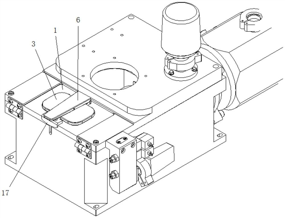
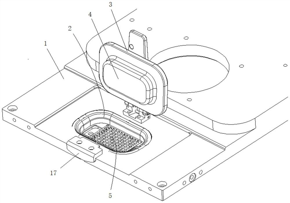
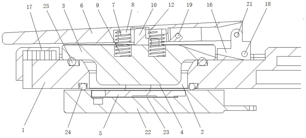
[0044] Such as figure 1Shown is a schematic structural diagram of an embodiment of the vacuum chamber of the present invention. The vacuum chamber of this embodiment includes a top cover 1 on which a hatch structure is arranged. Concretely, the hatch structure of the present embodiment comprises the sample-filling hole 2 arranged on the top cover 1 and the hatch 3 whose cover is installed on the outside of the sample-filling hole 2, the hatch 3 is provided with a protrusion 4, and the protrusion 4 When the hatch 3 cover is mounted on the sample hole 2, it extends inwardly into the sample hole 2, and the distance between the inner side of the protrusion 4 and the inner side of the...


PUM


Abstract

The invention discloses a cabin door structure. The cabin door structure comprises a sample adding hole formed in a top cover and a cabin door covering the outer side of the sample adding hole, wherein a bulge is arranged on the cabin door; the bulge extends inwards to extend into the sample adding hole when the cabin door covers the sample adding hole; and the distance between the inner side faceof the bulge and the inner side face of the top cover is smaller than the thickness of a sample adding target plate. According to the cabin door structure disclosed by the invention, the distance between the inner side face of the bulge and the inner side face of the top cover is set to be smaller than the thickness of the sample adding target plate, so that when the sample adding target plate isnot correctly mounted, the inner side face of the bulge and the sample adding target plate generate interference, and the cabin door cannot be normally closed; the cabin door structure disclosed by the invention can be used for detecting whether the sample adding target plate is correctly mounted in a target plate groove or not; and furthermore, when a mounting position of the sample adding target plate has a slight error, the bulge can be pressed on the sample adding target plate in a cabin door closing process and the sample adding target plate is pressed to be correct, so that the sample adding target plate is correctly mounted in the target plate groove and the cabin door structure also has the effect of correcting the error.

Description

technical field [0001] The invention relates to a vacuum chamber, in particular to a vacuum chamber and a hatch structure. Background technique [0002] The hatch structure of the existing vacuum chamber generally includes a sample injection hole arranged on the top cover and a hatch with a cover mounted on the outside of the sample injection hole. A sealing structure such as a sealing ring is provided between the hatch and the sample injection hole. When in use, move the target plate tray to the inside of the sample injection hole, open the hatch and place the target plate in the target plate groove of the target plate tray, then close the hatch and vacuumize. [0003] Although the hatch structure of the existing vacuum chamber can meet the requirements of use to a certain extent, it still has the following deficiencies: [0004] 1. It is impossible to detect whether the sample is correctly placed in the target plate slot, and when the target plate is not correctly instal...

Claims


Application Information

Patent Timeline
IPC IPC(8): E06B3/70E06B3/34E05B1/00E05F1/12G01N35/00G01N35/04
CPCE06B3/70E06B3/34E05B1/0015E05F1/12G01N35/00G01N35/04G01N35/00623G01N35/00712G01N2035/00306G01N2035/0403G01N2035/00643G01N2035/0491H01J2237/184C23C14/56H01J49/0495E05C19/16E05F1/1207G01N2035/00316G01N2035/0405
Inventor 潘能科汪云飞
Owner ZYBIO INC
Learn More