Rotor blade for wind turbine

A technology of wind turbines and rotor blades, applied to wind power engines, wind power generators consistent with the wind direction, engines, etc., can solve the problems of production and transportation of rotor blades, achieve easy alignment and assembly, simplify transportation and transportation, The effect of a mechanically secure connection

Pending Publication Date: 2020-12-15
SIEMENS GAMESA RENEWABLE ENERGY AS
View PDF0 Cites 1 Cited by
  • Summary
  • Abstract
  • Description
  • Claims
  • Application Information

AI Technical Summary

Problems solved by technology

This makes the production and transportation of rotor blades difficult

Method used


Image

  • Rotor blade for wind turbine
  • Rotor blade for wind turbine
  • Rotor blade for wind turbine

Examples


Embodiment Construction

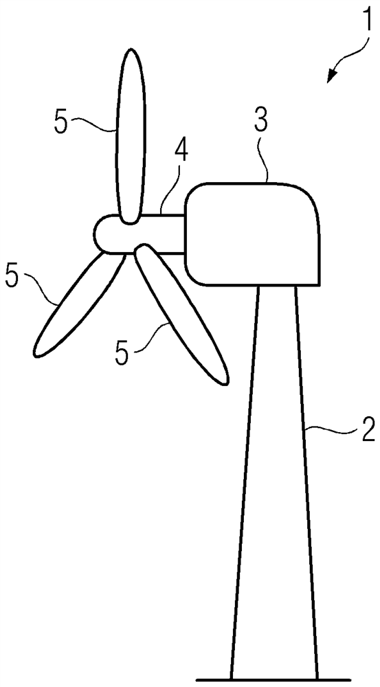
[0027] figure 1 An inventive wind turbine 1 is shown comprising a tower 2 together with a nacelle 3 and a hub 4 where in this embodiment three inventive rotor blades 5 are attached. As is well known, the rotor blades 5 interact with the wind, causing the hub 4 to rotate. This rotation drives a generator arranged in the nacelle 3 for generating electrical energy.

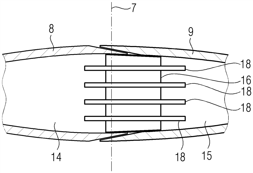
[0028] figure 2 A schematic sketch is shown in the form of an exploded view of a rotor blade 5 according to the first embodiment. In the following, a number of embodiments are described. The same reference numerals will be used for the same or comparable parts of the corresponding embodiments.

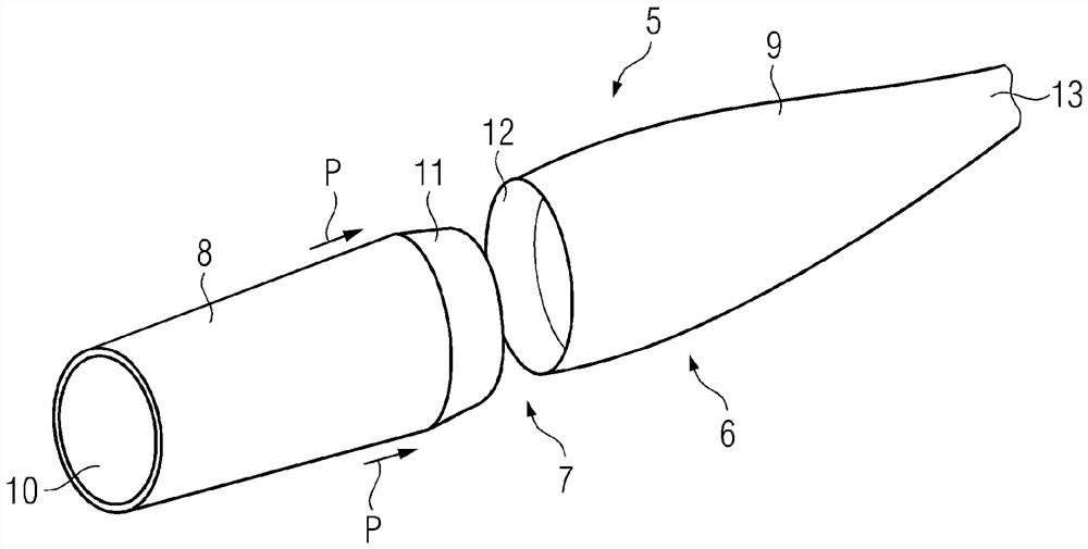
[0029] Such as figure 2 The rotor blade 5 shown in comprises a hollow blade body 6 which is divided along a division plane 7 into two body parts 8, 9 which, as indicated by the arrow P, can be pushed into in or connected to each other. The first blade body 8 extends from the root 10 to the first connection section 11...


PUM


Abstract

Rotor blade for a wind turbine, comprising a hollow blade body (6) with a root (10) and a tip (13), wherein the blade body (6) is split along a split plane (7) into two body parts (8, 9), one extending from the root (10) to a first connection (11) section and the other extending from a second connection (12) section to the tip (13), wherein the first and the second connection sections (11, 12) areadapted to overlap each other in the connected position.

Description

technical field [0001] The invention relates to a rotor blade for a wind turbine comprising a hollow blade body having a root and a tip. Background technique [0002] A wind turbine typically comprises at least two (in most installations three) rotor blades attached to a hub. The rotor blades interact with the wind, causing the hub to spin. When the hub is coupled to a generator, electrical power is generated, as is well known. [0003] Wind turbines are installed onshore, but offshore wind turbines are also known. Offshore wind turbines in particular have increased in size over the years. As the height of the wind turbine tower increases, the length of the rotor blades also increases. This makes the production and transportation of the rotor blades difficult. Contents of the invention [0004] It is an object of the invention to provide an improved rotor blade. [0005] In order to solve this problem, a rotor blade for a wind turbine is provided comprising a hollow ...

Claims


Application Information

Patent Timeline
Patent Type & Authority Applications(China)
IPC IPC(8): F03D1/06
CPCF03D1/0675F05B2240/302F05B2250/292Y02E10/72
Inventor C.布尔夏特A.赫鲁普M.尼尔森
Owner SIEMENS GAMESA RENEWABLE ENERGY AS
Why Eureka
Try Eureka