Valve body

A valve body, decorative panel technology, applied in valve details, valve device, valve shell structure and other directions, can solve the problem of difficult to precisely control the welding position of the decorative panel.

Pending Publication Date: 2020-12-15
HANGZHOU XIAOMI ENVIRONMENTAL SCI & TECH
View PDF0 Cites 0 Cited by
  • Summary
  • Abstract
  • Description
  • Claims
  • Application Information

AI Technical Summary

Problems solved by technology

[0003] The problem to be solved by the present invention is to provide a valve body, which solves the probl

Method used


Image

  • Valve body
  • Valve body
  • Valve body

Examples


Embodiment Construction

[0020] The technical solutions of the embodiments of the present invention will be explained and described below in conjunction with the accompanying drawings of the embodiments of the present invention, but the following embodiments are only preferred embodiments of the present invention, not all of them. Based on the examples in the implementation manners, other examples obtained by those skilled in the art without making creative efforts all belong to the protection scope of the present invention.

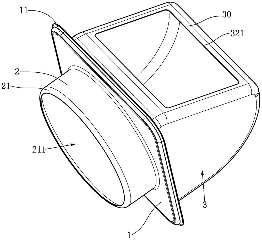
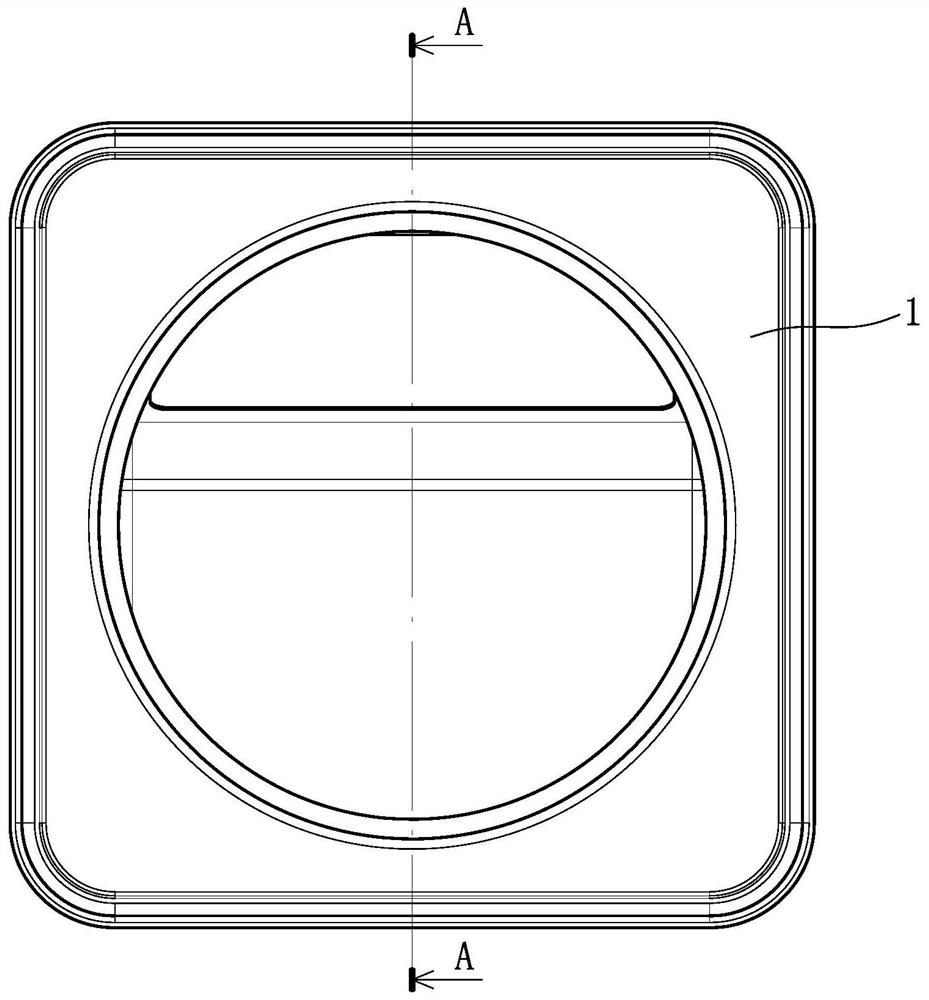
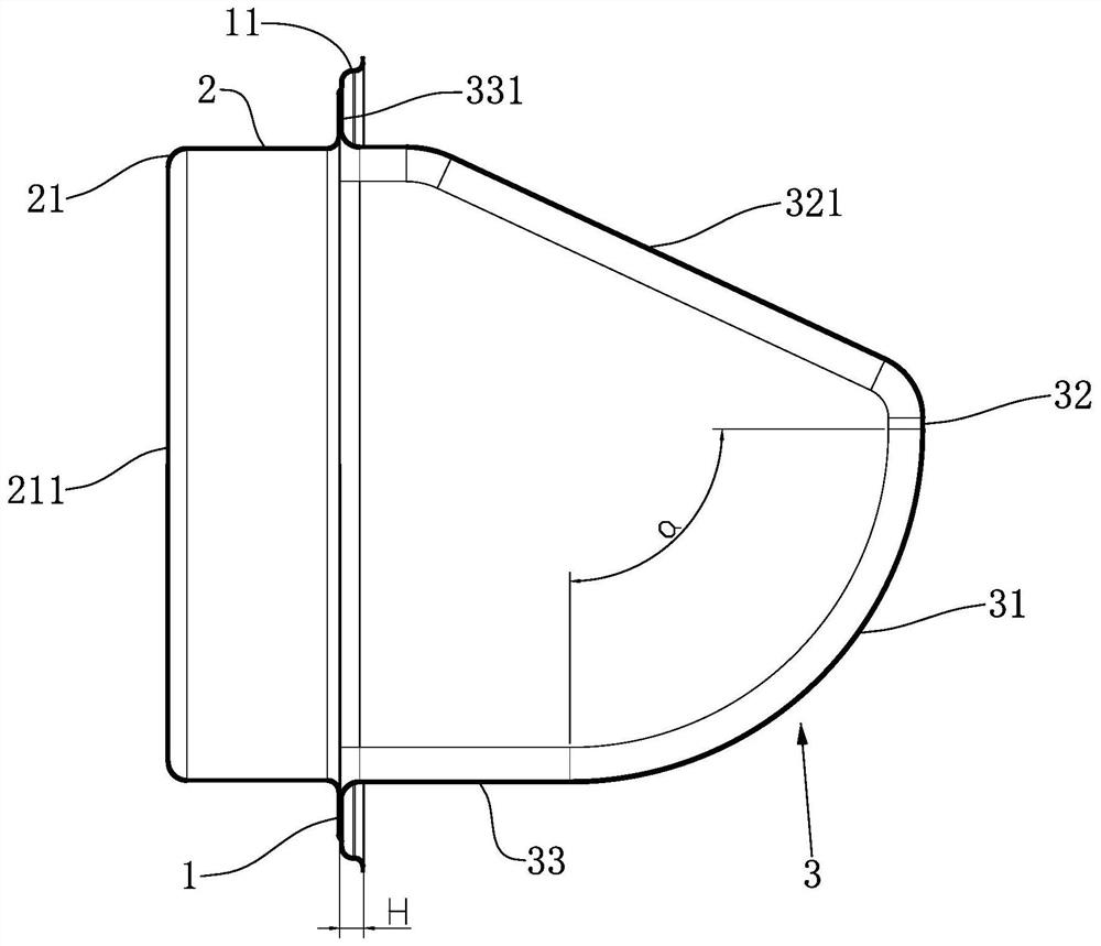
[0021] see figure 2 with image 3 , the valve body includes a ring-shaped pipe, and the ring-shaped pipe is arranged in sequence along the exhaust direction with a socket pipe 2, a decorative panel 1 and an exhaust pipe 3. The projection of the exhaust pipe 3 in the vertical direction is located in the decorative panel 1, and the socket pipe 2 An air inlet 211 is provided, an exhaust port 321 is provided on the exhaust pipe 3 , the exhaust pipe 3 includes an inclined section 3...


PUM


Abstract

The invention relates to a valve body, and solves the problem that the welding position of a decorative panel on an annular sleeve is difficult to control accurately. The valve body comprises an annular pipeline, an inserting pipe, the decorative panel and an exhaust pipe, the inserting pipe, the decorative panel and the exhaust pipe are sequentially arranged on the annular pipeline in the exhaustdirection, an air inlet is formed in the inserting pipe, an exhaust port is formed in the exhaust pipe, the exhaust pipe comprises an inclined section, the inclined section extends upwards, the exhaust port is located above the inclined section, and the valve body is characterized in that the inserting pipe is arranged on the decorative panel in a manner different from the exhaust pipe.

Description

technical field [0001] The invention relates to a valve body. Background technique [0002] The existing valve body includes a decorative panel and an annular sleeve. The annular sleeve is provided with an air inlet and an exhaust port. After the decorative panel is sleeved in the middle of the annular sleeve, the two are connected as a whole by welding. However, it is difficult to accurately control the welding position of the decorative panel on the annular sleeve. Contents of the invention [0003] The problem to be solved by the present invention is to provide a valve body, which solves the problem that the welding position of the decorative panel on the annular sleeve is difficult to precisely control. [0004] In order to solve the above problems, the present invention provides the following technical solutions: [0005] The valve body includes an annular pipeline, and the annular pipeline is provided with a socket pipe, a decorative panel and an exhaust pipe in se...

Claims


Application Information

Patent Timeline
IPC IPC(8): F16K27/00
CPCF16K27/00
Inventor 王启定曹正祥
Owner HANGZHOU XIAOMI ENVIRONMENTAL SCI & TECH
Why Eureka
Try Eureka