
Stranding and cabling device for optical cable production

A technology for optical cables and racks, applied in the field of optical cable production, can solve the problems of poor tensile resistance, larger pitch of optical cables, and increased production costs of optical cables, so as to prevent self-rotation, good anti-rotation effect, and convenient loading Effect

Active Publication Date: 2020-12-15
安徽龙联智能光电有限公司
View PDF8 Cites 0 Cited by
  • Summary
  • Abstract
  • Description
  • Claims
  • Application Information

AI Technical Summary

Problems solved by technology

The self-rotation of the optical cable is called untwisting, and the untwisting will cause the pitch of the formed optical cable to increase, and the tensile resistance will deteriorate, thereby indirectly increasing the production cost of the optical cable.

Method used


Image

  • Stranding and cabling device for optical cable production
  • Stranding and cabling device for optical cable production
  • Stranding and cabling device for optical cable production

Examples


Embodiment 1

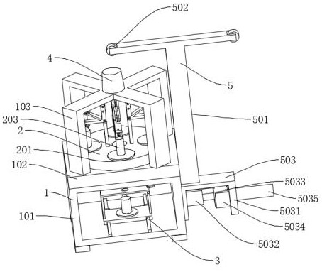
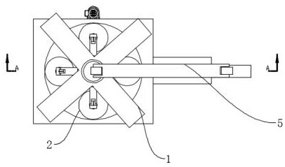
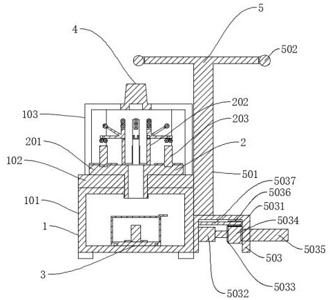
[0035] Such as Figure 1-7 As shown, a stranding device for optical cable production includes a support mechanism 1 and a winding mechanism 5. The support mechanism 1 is mainly composed of a support frame 101, a working plate 102, and a frame 103, and also includes a stranding mechanism 2, Placement mechanism 3, anti-retraction mechanism 4, twisting mechanism 2 includes a rotating plate 201, a guide frame 202, a first placement frame 203, the center of the rotating plate 201 is provided with a through-wire hole 1, and the rotating plate 201 is rotatably connected to the top of the working plate 102 , and the bottom of the rotating plate 201 is provided with a bump, which runs through the working plate 102 and is connected to the motor through a chain. The top of the rotating plate 201 is rotatably connected to the first placement frame 203, and the inside of the first placement frame 203 is provided with a guide frame. 202, such setting can drive the rotating plate 201 to rota...

Embodiment 2

[0038] Such as Figure 8 As shown, the difference between Embodiment 2 and Embodiment 1 is that: the end of the guide bracket 2023 close to the rotating seat 2022 is provided with a mounting groove 2027, and a locking screw 20201 is arranged under the mounting groove 2027, and the lower end of the locking screw 20201 passes through the guide The bracket 2023 extends into the rotating base 2022 and is threadedly connected with the rotating base 2022. In this way, the locking screw 20201 can be rotated so that the locking screw 20201 can extend into the rotating base 2022 to realize the function of fixing the guide bracket 2023.

[0039]In the above structure, when in use, the cylinder 303 is first activated, the cylinder 303 drives the slide plate 302 to slide outside the slide rail 301, and the slide plate 302 drives the second placement frame 304 to move, so that the slide plate 302 moves out of the support frame 101, and the top plate 306 can also be flipped, Make the top pl...


PUM


Abstract

The invention discloses a stranding and cabling device for optical cable production, which comprises a supporting mechanism and a winding mechanism, wherein the supporting mechanism mainly comprises asupporting frame, a working plate and a rack. The stranding and cabling device is characterized by further comprising a stranding mechanism, a placing mechanism and an anti-back-twist mechanism, wherein the stranding mechanism comprises a rotating plate, a guide frame and a first placement frame, a wire through hole I is formed in the center of the rotating plate, the rotating plate is rotationally connected to the top of the working plate, a protruding block is arranged at the bottom of the rotating plate, the protruding block penetrates through the working plate and is connected to a motorthrough a chain, and the first placement frame is rotationally connected to the outer side of the top of the rotating plate. Through the arrangement of the placement mechanism, the function of facilitating feeding is achieved; the whole anti-back-twist mechanism is small in structure, simple in structure and close to the rack, so that the self-rotation of the optical cable can be effectively prevented, and the anti-rotation effect is good.

Description

technical field [0001] The invention relates to the technical field of optical cable production, in particular to a stranding device for optical cable production. Background technique [0002] Stranded cables are made with a sleeve wound helically around a strength member. When the casing is spirally wound on the reinforcement, one is left-handed, which looks like "S", also known as S-direction; the other is right-handed, which is shaped like "Z", also known as Z-direction. The twisted cabling method of replacing direction is called SZ twisted cabling. The cable forming speed of SZ stranded cable is faster, and the length of the produced optical cable is longer. With the progress of the times, SZ stranded cable has been widely used in the production of twisted optical cable. [0003] The function of the traditional sizing die is to limit the diameter of the optical cable. When SZ is twisted into a cable, because the twisting head will produce a certain torsional force whe...

Claims


Application Information

Patent Timeline
IPC IPC(8): G02B6/44
CPCG02B6/449
Inventor 卢立建
Owner 安徽龙联智能光电有限公司
Learn More