Hairtail processing device
A processing device and hairtail technology, which is applied in processing fish, cutting fish into portions, cleaning hollow objects, etc., can solve problems such as inability to cut hairtail in batches, and achieve the effects of improving convenience, saving procedures, and reducing complexity
- Summary
- Abstract
- Description
- Claims
- Application Information
AI Technical Summary
Problems solved by technology
Method used
Image
Examples
specific Embodiment approach 1
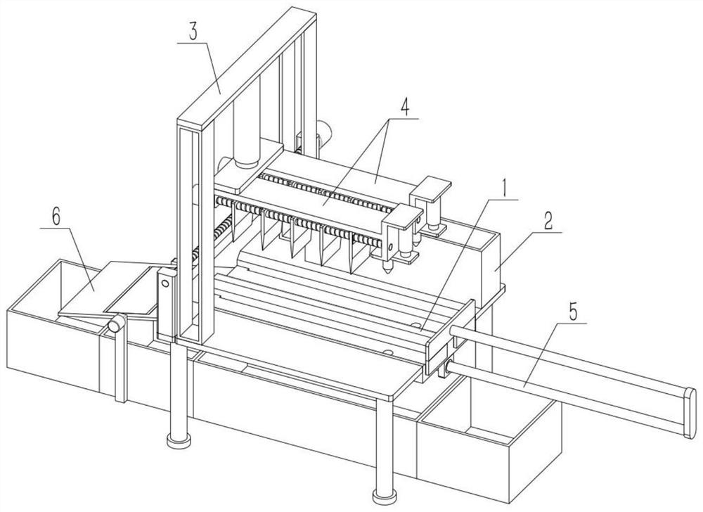
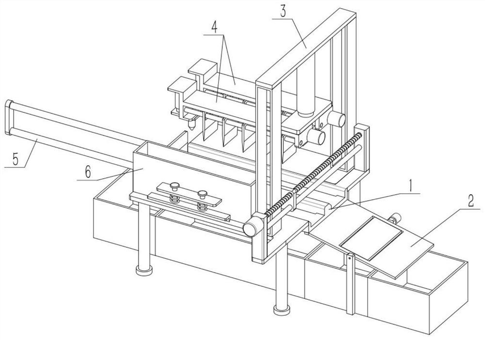
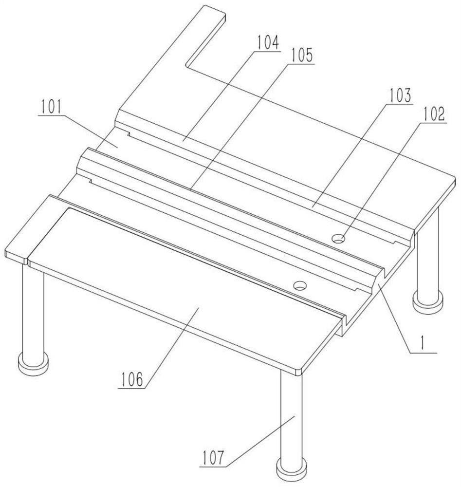
[0029] As shown in the figure, a hairtail processing device includes a processing table 1, a placement groove 101 and a positioning hole 102. The upper end of the processing table 1 is provided with a plurality of evenly distributed placement grooves 101 from front to back. Positioning holes 102 are provided, and the number of positioning holes 102 is the same as that of the placement slots 101 , and the plurality of positioning holes 102 are respectively located in the middle of the right side of the plurality of placement slots 101 . The width of placing groove 101 is close to the width of hairtail, and the length of placing groove 101 is longer than the length of hairtail. A hairtail is placed in each placement groove 101, and the head of the hairtail is located at the positioning hole 102, and the hairtail is positioned by inserting a rod-shaped member into the positioning hole 102, so that the hairtail is processed at a fixed point. The depth of placement groove 101 is cl...
specific Embodiment approach 2
[0031] As shown in the figure, the hairtail processing device also includes a laminating plate 106, a support portion 107, a heat preservation bin 2, a connecting portion 201, a screw I202, a round rod I203, a column 204 and a motor I205, and the front and rear ends of the processing table 1 are fixed. Connect a fitting plate 106, the lower end of each fitting plate 106 is all affixed to the support portion 107, the lower end surface of the heat preservation bin 2 is slidably fitted with the fitting plate 106, the connecting portion 201 is fixed on the left end of the heat preservation bin 2, and the connecting portion 201 is threaded. Connected to the lead screw I202, the connecting part 201 is slidably connected to the round rod I203, and there are two columns 204. On the two columns 204, the output shaft of the motor I205 is fixedly connected to one end of the lead screw I202, the motor I205 is fixedly connected to the column 204 at the corresponding position, and the two co...
specific Embodiment approach 3
[0033]As shown in the figure, the processing table 1 is provided with a reversed surface 104 and an arcuate surface 105 , and the inverted surface 104 and the arcuate surface 105 are respectively located at the edges of the upper end, the front end, and the front end of the placing groove 101 . The inverted surface 104 is convenient for the hairtail at the lowermost end of the thermal insulation storehouse 2 to be slightly inclined when passing the inverted surface 104, and then can be obliquely inserted into the placement groove 101, so as to prevent the fatter hairtail from accidentally skipping the placement groove 101. The arc surface 105 can make the hairtail at the lowermost end of the thermal insulation storehouse 2 be subjected to an oblique upward support force when passing through, so as to prevent two hairtails from being squeezed in a placement groove 101. Because the depth of the placement groove 101 is close to the thickness of a hairtail, the two hairtails squeeze...
PUM
 Abstract
Description
Claims
Application Information
 - R&D
- Intellectual Property
- Life Sciences
- Materials
- Tech Scout
- Unparalleled Data Quality
- Higher Quality Content
- 60% Fewer Hallucinations
Browse by: Latest US Patents, China's latest patents, Technical Efficacy Thesaurus, Application Domain, Technology Topic, Popular Technical Reports.
© 2025 PatSnap. All rights reserved.Legal|Privacy policy|Modern Slavery Act Transparency Statement|Sitemap|About US| Contact US: help@patsnap.com


