Efficient drainage device for clinical nursing

A high-efficiency, shell technology, applied in the application, suction equipment, medicine equipment and other directions, can solve the problem of overfilling the drainage bucket and achieve the effect of reducing air pressure

Inactive Publication Date: 2020-12-18
李鸿兴
View PDF1 Cites 2 Cited by
  • Summary
  • Abstract
  • Description
  • Claims
  • Application Information

AI Technical Summary

Problems solved by technology

The nursing drainage device used in the intensive care unit of the ICU in the above-mentioned patent has the following disadvantages: although the alarm can be used to alarm, but because the drainage pump is used, it is inevitable that there will be liquid in the connecting pipe and the drainage pipe entering the drainage barrel. If the liquid in the bucket cannot be drained in time, the liquid in the drainage bucket will be overfilled

Method used


Image

  • Efficient drainage device for clinical nursing
  • Efficient drainage device for clinical nursing
  • Efficient drainage device for clinical nursing

Examples


Embodiment Construction

[0028] The technical solution of this patent will be further described in detail below in conjunction with specific embodiments.

[0029] Embodiments of the present patent are described in detail below, examples of which are shown in the drawings, wherein the same or similar reference numerals designate the same or similar elements or elements having the same or similar functions throughout. The embodiments described below by referring to the figures are exemplary and are only used for explaining the patent, and should not be construed as limiting the patent.

[0030] In the description of this patent, it is to be understood that the terms "center", "upper", "lower", "front", "rear", "left", "right", "vertical", "horizontal", The orientation or positional relationship indicated by "top", "bottom", "inner", "outer", etc. is based on the orientation or positional relationship shown in the drawings, and is only for the convenience of describing this patent and simplifying the des...


PUM


Abstract

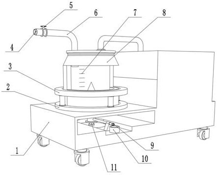
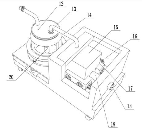
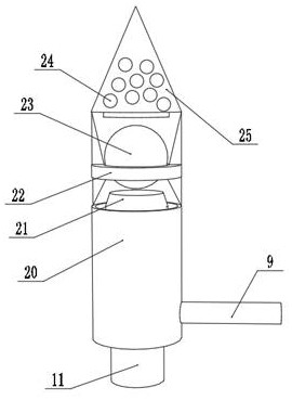
The invention discloses an efficient drainage device for clinical nursing, and relates to the technical field of clinical nursing equipment. The efficient drainage device for clinical nursing aims atsolving the problem that too much liquid in a collecting barrel cannot be quickly drained. The efficient drainage device for clinical nursing specifically comprises a shell, a collecting barrel and awater level detector, wherein rubber is arranged on the inner wall of the bottom of the collecting barrel, a liquid drainage pipe is clamped to the inner wall of the rubber, the bottom of the liquid drainage pipe is fixed to the inner wall of the bottom of the shell, a first cone is clamped to the outer wall of the top of the liquid drainage pipe, and two or more leakage openings are formed in theinner wall of the first cone. According to the efficient drainage device for clinical nursing, the liquid drainage pipe is arranged, when the water level detector detects that too much liquid existsin the collecting barrel, an electric push rod can be controlled, a ball body is separated from the first cone, enters a slope on the top of a clamping ring and does not make contact with the top of the clamping ring, then liquid can enter a groove in the liquid drainage pipe and flows out of a water outlet pipe to enter a collecting cup, liquid in the collecting barrel is reduced, the collectingbarrel is not full of liquid, and meanwhile, liquid in the collecting barrel can be sampled when the device works.

Description

technical field [0001] The invention relates to the technical field of clinical nursing equipment, in particular to a high-efficiency drainage device for clinical nursing. Background technique [0002] When performing drainage for surgical patients, a negative pressure drainage device is usually used. The so-called negative pressure drainage device is to form a pressure difference between the pressure in the drainage device and the pressure of the drainage site, so as to drain the liquid or secretion to the drainage through the pressure difference. inside the device. [0003] After searching, the Chinese application publication number is CN111068126A, which discloses a nursing drainage device for ICU intensive care medicine department, including a bottom plate and a drainage device main body arranged on the top of the bottom plate, and a tray is arranged on the top of the drainage device main body , the upper part of the main body of the drainage device is movably equipped ...

Claims


Application Information

Patent Timeline
Patent Type & Authority Applications(China)
IPC IPC(8): A61M1/00A61B10/00
CPCA61M1/0023A61B10/0045A61M2205/15A61M2205/18A61M2205/3386A61M1/78
Inventor 李鸿兴马广庆
Owner 李鸿兴
Why Eureka
Try Eureka