
Automatic sand and gravel bagging machine

A bagging machine and sand and gravel material technology, which is applied in the field of automatic sand and gravel material bagging machines, can solve the problems of manual control of bagging volume, poor bagging efficiency, and poor bagging, so as to achieve smooth discharge and accurate measurement , High bagging efficiency

Inactive Publication Date: 2016-11-30
许陈菲
View PDF0 Cites 9 Cited by
  • Summary
  • Abstract
  • Description
  • Claims
  • Application Information

AI Technical Summary

Problems solved by technology

[0004] Although the above-mentioned patent application can achieve automatic bagging to a certain extent, the bagging efficiency is poor. After the sand and gravel are discharged from the hopper, they need to pass through an L-shaped discharge pipe, that is, the sand and gravel need to pass through a horizontal pipe, and then pass through After the bending part, finally fall vertically
Despite the function of the screw propulsion device, the sand and gravel are easy to accumulate in the horizontal pipe or the bending part, resulting in material blockage, and then the bagging is not smooth
In addition, the amount of bagging needs to be manually controlled

Method used


Image

  • Automatic sand and gravel bagging machine
  • Automatic sand and gravel bagging machine

Examples


Embodiment Construction

[0024] The present application will be further described in detail below in conjunction with the accompanying drawings and specific preferred embodiments.

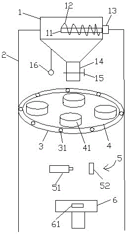
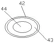
[0025] like figure 1 and figure 2 As shown, an automatic bagging machine for sand and gravel, which has a hopper 1, a stirring rod 11, a propeller blade 12, a motor 13, a discharge port 14, a solenoid valve 15, a vibrating pendulum 16, a fixing frame 2, and a turntable fixing seat 3. Bearing 31, turntable 4, woven bag fixing seat 41, electromagnet 42, metal pressing block 43, through hole 44, sealing machine 5, sealing head 51, nail plate 52, jacking platform 6 and load cell 61 and other main technical features.

[0026] An automatic sand and gravel bagging machine includes a hopper, a fixing frame, a rotating disk fixing seat, a rotating disk, a binding machine and a jacking platform.

[0027] The hopper is set at the top center of the fixed frame, and a horizontal stirring rod is set inside the hopper, and a propelle...


PUM


Abstract

The invention discloses an automatic sand and gravel bagging machine which comprises a hopper, a fixed frame, a rotating plate fixing base, a rotating plate, a tying machine and a jacking table. A discharge port is formed in the bottom of the hopper and provided with an electromagnetic valve. A vibration swing hammer is arranged on the side wall of the hopper or the fixed frame. The rotating plate fixing base is coaxially arranged below the hopper. The outer side wall of the rotating plate fixing base is fixedly connected with the fixed frame. A plurality of woven bag fixing bases are arranged on the rotating plate. Each woven bag fixing base comprises a through hole, an electromagnet and a metal pressing block, wherein when the electromagnet is powered on, the metal pressing block can attract the electromagnet. The tying machine is arranged below the rotating plate and coaxial with the discharge port. The tying machine comprises an opening sealing machine head and a nail plate. A weighing sensor connected with the electromagnetic valve is arranged on the jacking table. By means of the machine, material blockage can not easily happen, blocking materials or wall-sticking materials can be automatically removed, the bagging amount can be automatically controlled, and bagging efficiency is high. The automatic opening sealing operation of sand and gravel bags can be achieved, opening sealing efficiency is high, opening sealing quality is good, and material leakage can not easily happen.

Description

technical field [0001] The present application relates to a bagging device, in particular to an automatic bagging machine for sand and gravel. Background technique [0002] In the flood fighting and emergency rescue of river courses and embankment projects, especially in the case of major floods, a large number of woven bags filled with sand and gravel materials are required when embankment projects rush to repair sub-dikes and plug leaks. Large, low efficiency, not suitable for flood fighting and emergency rescue. [0003] The Chinese utility model patent application with the application number 2014208342479 published on May 13, 2015, the name of its invention is "an automatic sand and gravel bagging machine", which includes a hopper, a discharge pipe connected to the lower end of the hopper, and a discharge pipe A screw propulsion device is installed inside, one end of the screw propulsion device has a pulley, the pulley is connected to the motor through a belt, the other...

Claims


Application Information

Patent Timeline
IPC IPC(8): B65B1/08B65B1/32B65B43/50B65B43/54B65B51/08B65D88/66B02C18/14
CPCB65B1/08B02C18/14B65B1/32B65B43/50B65B43/54B65B51/08B65D88/66
Inventor 许陈菲
Owner 许陈菲
Learn More